Home
Elcometer
Test Equipment
1535
Page 19
Elcometer 1535 - Page 19
25 pages
Manual
Save Page as PDF
To Next Page
To Next Page
To Previous Page
To Previous Page
Loading...
17
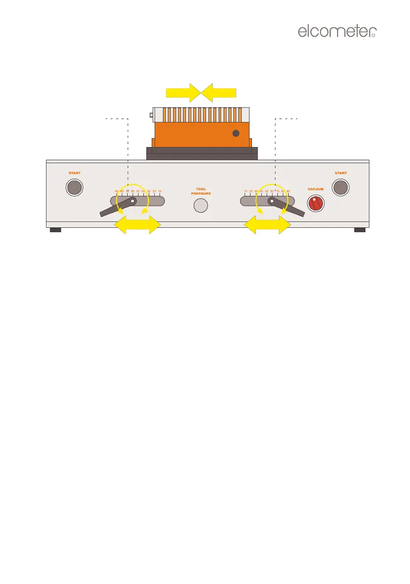
3.
Lo
osen
the
start
and
stop
position
handles,
slide
them
to
the
required
positions and
then tighten.
Figure 12. Sett
ing scratch le
ngth
Start position
Stop position
adjustment
adjustment
O
p
_
1
5
3
5
_
0
1
A
5
.
f
m
P
a
g
e
1
7
W
e
d
n
e
s
d
a
y
,
A
u
g
u
s
t
8
,
2
0
0
7
3
:
5
9
P
M
18
20
Table of Contents
Main Page
Default Chapter
3
Table of Contents
3
1 About Your Tester
4
Standards
5
What the Box Contains
5
2 Getting Started
6
The Parts of the Instrument
6
Connecting to a Compressed Air Supply
7
Caution
8
3 Scratching Tools
8
Selecting a Scratching Tool
8
Tungsten Carbide DIN Tool
9
Other Tools
10
Removing and Fitting a Scratching Tool
11
Checking and Adjusting the Angle of the Tool Holder
13
4 Mounting a Specimen
15
Ferrous (Magnetic) Specimens
15
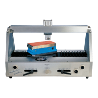
Non-Ferrous Specimens (Using Optional Vacuum Table)
17
5 Setting the Scratch Angle
18
6 Setting the Scratch Length
18
7 Testing a Specimen
20
8 Air Pressure/Force
22
9 Maintenance
22
10 Technical Specification
23
11 Spare Parts and Accessories
24
12 Related Equipment
25
Related product manuals
Elcometer 108
20 pages
Elcometer 510
168 pages
Elcometer 506
113 pages