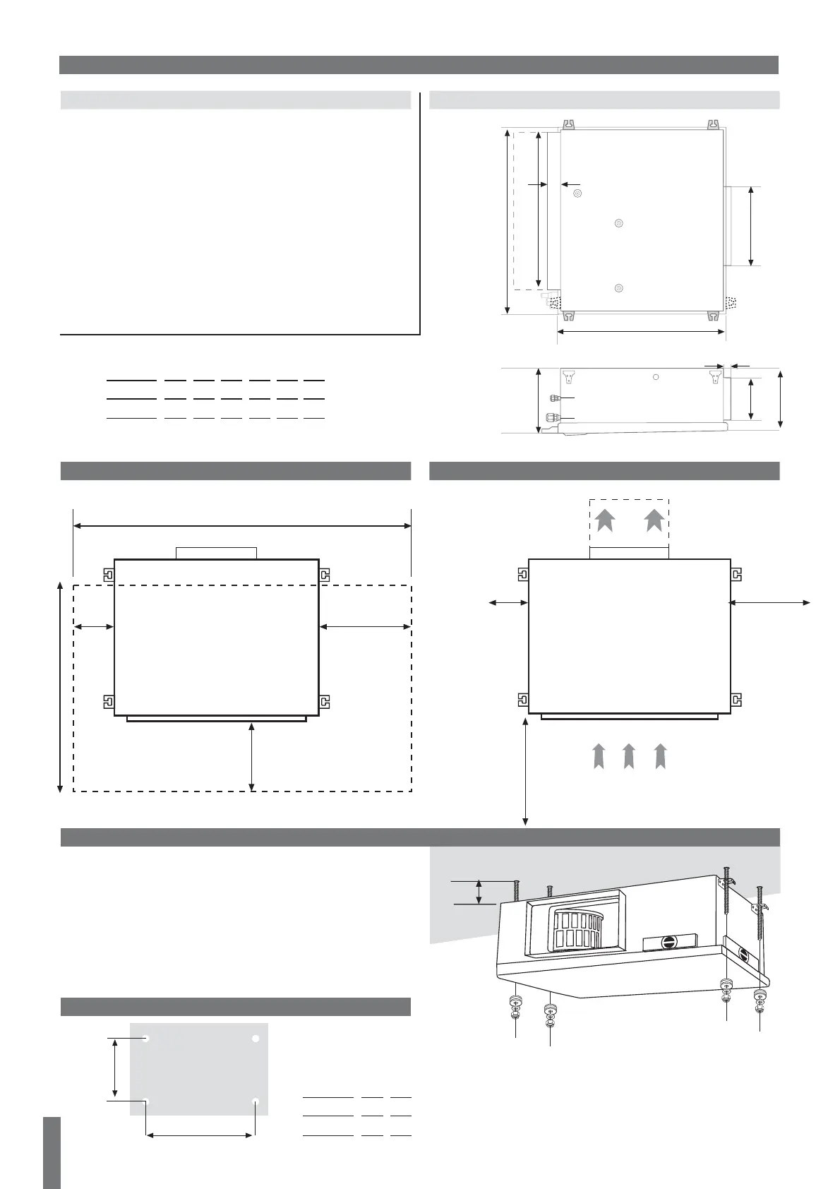
5mm
While selecting a place for the indoor unit:
a. Allow max. air flow to the desired space
b. Allow max return air flow
c. Ensure adequate drainage of condensed water
d. Ensure noise reduction near bedrooms
e. Leave a minimum 250 mm free space in front of the filter
f. Allow a free service access to electrical box.
h. Allow easy access to the base of the indoor unit while providing
enough space from the ceiling
i. Use serrated rubber under the unit and flexible joints to avoid
resonance vibrations
UNIT INSTALLATION
a. Insert 4 M10 or 3/8” threads rodes into the ceiling.
b. Introduce the rodes through the slots of unit suspension brackets.
c. Position the shock absorbers, add washers and screw the nuts
until the unit is firmly supported.
d. In case of a gap between the unit and the ceiliing, put a rubber or
a neoprene sheet.
IMPORTANT The unit must be perfectly levelled
50mm
250mm
200mm
*50mm
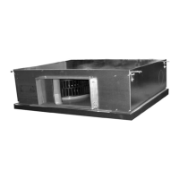
INDOOR UNIT
6
50mm
100 mm
200mm
*50mm
700mm
1100 (*900) mm
* In case control box is dismounted from the unit * In case control box is dismounted from the unit
CLEARENS AROUND THE UNITACCESS TO THE UNIT
CAP.
5-9 Kw
10-16 Kw
A
797
861
B
599
663
B
A
HOLES DRILLING LOCATION ON THE CEILLING FOR INDOOR UNIT
UNIT LOCATION
UNIT DIMENTIONS
F
E
70 8 0
D
61
C
A
B
359
CAP.
5-9 Kw
10-13 Kw
14-16 Kw
A
790
854
854
B
653
715
715
C
749
816
816
E
162
193
233
F
242
282
322
D
256
297
337
36