1. Indoor unit
2. Outdoor unit
3. Power supply cable
4. Control cable (2 x 0.5mm
2
)
5. Display connector
6. Display unit
7. Wireless remote control
8. Inter connecting cable (5 x 2.5mm
2
)
1PH Units Power supply to indoor
(5Kw units)
CLOCK
OUT
L3
L2
L
L1
L
N45
6N
89
NL L N
456
For Heat-pump units only
1
2
3
4
5
6
7
8
10
20A
20A
25A
25A
5kw
7kw
9kw
10.5kw
POWER SUPPLY
CABLE
3 X 2.5MM
2
3 X 2.5MM
2
3 X 4MM
2
3 X 4MM
2
CIRCUIT BRAKER
1PH UNITS
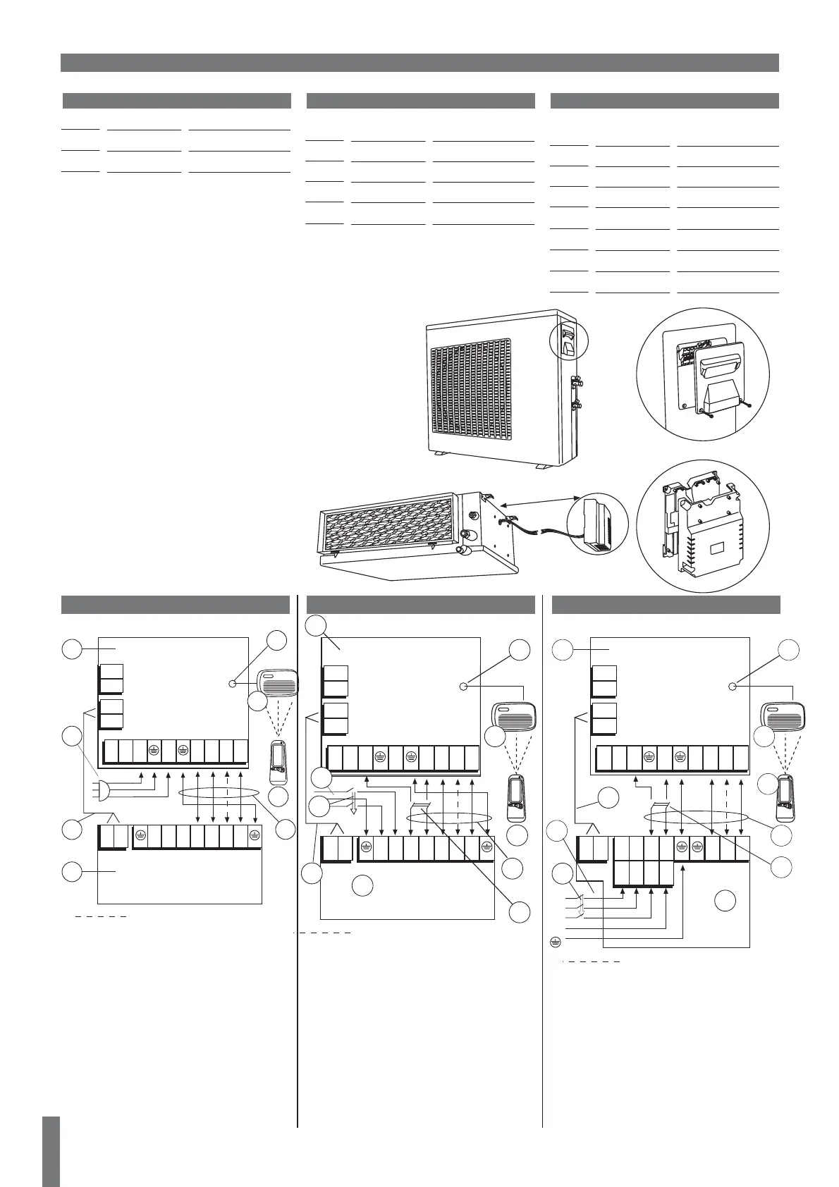
ELECTRICAL SPECIFICATIONS
All conductors should be of size and number as indicated in this page.
Electrical cable should be in one piece without any joints. When mounting
the cable under the floor please make sure it is perfectly protected and
isolated from any possible contact with water. When the cable path runs
through a wall or an acoustic ceiling, it must be protected with fireproof
tubing. In addition, a telephone type cable, 2 x 0.5 mm, should interconnect
the two units.
1. Indoor unit
2. Outdoor unit
3. Power supply cable
4. Control cable (2 x 0.5mm
2
)
5. Display connector
6. Display unit
7. Wireless remote control
8. Inter connecting cable (6 x 1.5mm
2
)
9. Safety Switch ON-OFF (by installer)
10. Circuit breaker (by installer)
3PH Units Power supply to outdoor
CLOCK
OUT
L3
L2
L
L1
L
N45
6N
89
L1 N
456
For Heat-pump units only
1
2
3
4
5
6
7
8
10
9
L2L3
L1 NL2L3
L1
L2
L3
N
For main power supply and interconecting use
only cable H05VV-K5G type. Allways follow
local national wiring standards regulation.
ELECTRICAL CONNECTIONS
1.8 m
CIRCUIT BRAKER
5kw
7kw
9kw
10.5kw
12.5kw
14kw
16kw
POWER SUPPLY
CABLE
5 X 1.5MM
2
5 X 1.5MM
2
5 X 2.5MM
2
5 X 2.5MM
2
5 X 2.5MM
2
5 X 2.5MM
2
5 X 2.5MM
2
3PH UNITS
3 X 10A
3 X 10A
3 X 16A
3 X 16A
3 X 16A
3 X 16A
3 X 20A
NOMINAL
230/50/1
400/50/3
1PH
3PH
VOLTAGE LIMITS
198-264V
360-440V
POWER SUPPLY
1. Prepare the multiple wire cable ends for
connection.
2. Take away the Indoor/outdoor cover and
open the terminals, take away the cable
clamp screw and turn over the cable clamp.
3. Connect the cable ends to the terminals of
the indoor and outdoor units.
4.
Connect the other end of the twin wire cable
to the outdoor unit twin wire terminal.
5. Secure the multiple wire power cable with
the cable clamps.
6. Fasten the twin wire cable to the power
cable with cable ties.
1. Indoor unit
2. Outdoor unit
3. Power supply cable
4. Control cable (2 x 0.5mm
2
)
5. Display connector
6. Display unit
7. Wireless remote control
8. Inter connecting cable (5 x 2.5mm
2
)
9. Safety Switch ON-OFF (by installer)
10. Circuit breaker (by installer)
1PH Units Power supply to outdoor
(7, 9, 10.5Kw units)
CLOCK
OUT
L3
L2
L
L1
L
N45
6N
89
NLLN
456
For Heat-pump units only
1
2
3
4
5
6
7
8
10
9
CAP. CAP.