2.8 Install the Interface Circuit for Flap and Trim Pots (Optional):
Elevator, Aileron and Rudder trim (as well as Flap position) can be monitored and displayed on the MVP. In most
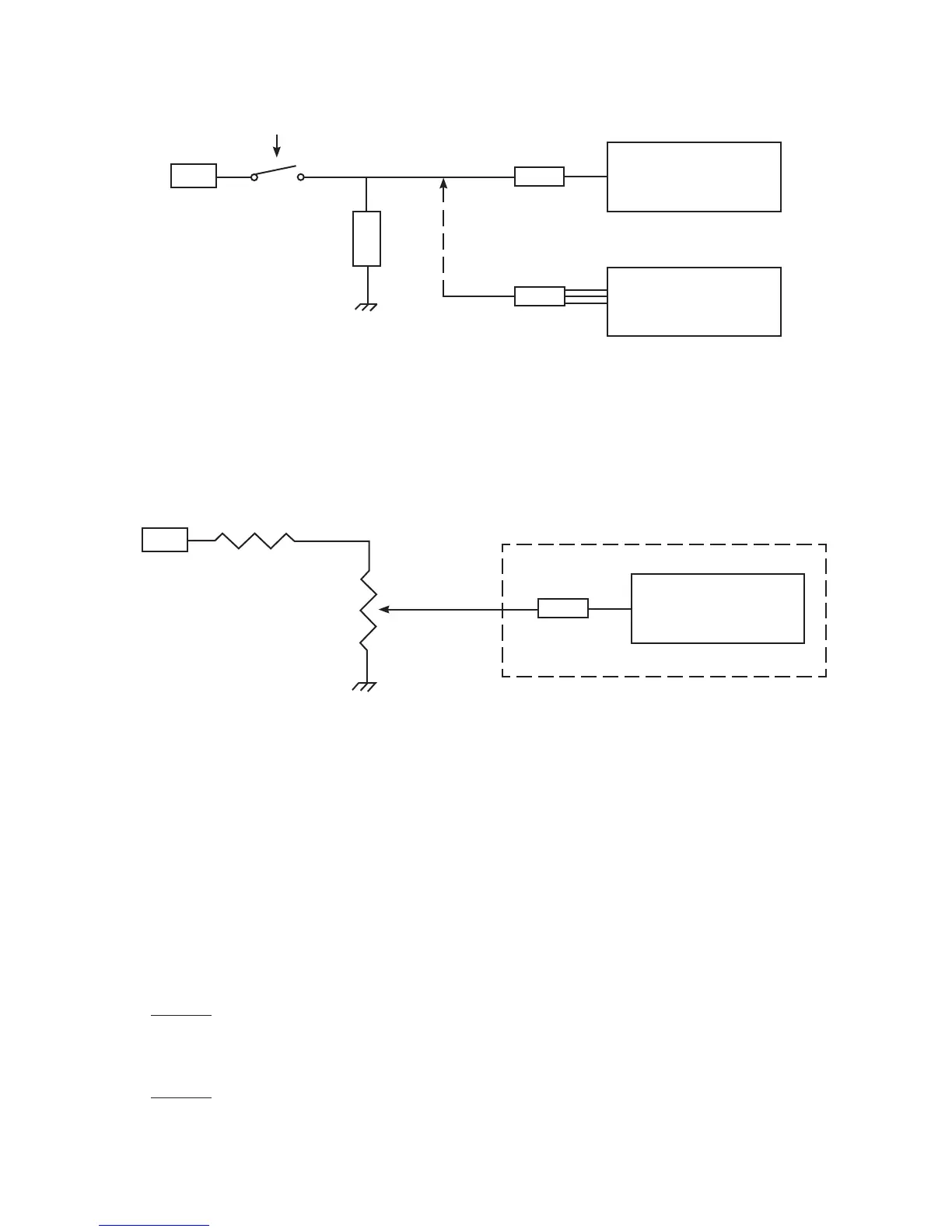
cases the position of these surfaces are monitored using a Ray Allen 5K ohm pot. The following circuit may be used
to interface with a 1K to 100K pot.
2.9 Install the Interface Circuit for the Gear Position, Unsafe Indicator and Gear
Warning (Optional):
The Gear Position and Unsafe Indicator shown on the MVP System Screen is intended as a backup to the aircraft’s
existing system. The Gear Warning operates off the Gear Position, Unsafe Indicator, Airspeed and Manifold Pressure.
The Gear Warning provides a voice warning to reduce the possibility of gear up landings.
Unsafe Indicator: Operates from an unsafe signal from the aircraft. Displays as either Red or Off on the
MVP. The EDC interface circuit is shown below. The Unsafe Indicator is REQUIRED with any landing
gear options listed below and requires one EDC input.
Landing Gear Position: There are three options for interfacing the EDC to the aircraft’s gear system.
Option 1: Connect the EDC to the aircraft’s Right, Left and Nose Gear green down lights. The state of
each gear will be displayed independently on the MVP. Select Gear Left, RT and Nose for the probes in
Configuration Screen #1. This option requires three EDC inputs. The EDC interface circuit is shown below.
Option 2: Connect the EDC to the aircraft’s Nose Gear green down light. The state of all three gears will
be displayed on the MVP based on the Nose Gear’s state. Select “Gear All” for the probe in Configuration
Screen #1. This option requires one EDC input. The EDC interface circuit is shown below.
EDC
Temp or Resistive Fuel
Level Channel
VI-221
Ray Allen
Pot
4.99K, 1%, 1/4W Resistor
1K to
100K
Bus
EDC
Temp or Resistive Fuel
Level Channel
EDC
Pressure Channel
Bus
VI-221
VI-221P
Switch or Relay
OR
Load
C. Switch to Bus with Load Referenced to Ground
15

 Loading...

