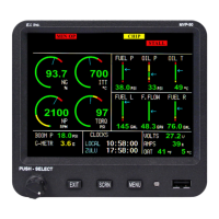
2.18 Install the Master Warning (red) and Caution (yellow) Lights (Optional):
The Warning and Caution Lights do not have to be installed unless the MVP is installed more than 8" from the pilot’s
visual centerline.
A. Locate the Red (AL-1R) and Yellow (AL-1Y) lights in the kit. Find an
appropriate mounting location within 8" of the pilot's visual centerline. The
lights will require 3/4" clearance behind the aircraft instrument panel.
B. Mark the aircraft instrument panel and drill a 5/16" hole for each light.
Install the Red Warning Light and the Yellow Caution Light from behind the
aircraft instrument panel.
Note: If the MVP Master Warning and Caution Outputs are connected to other lights or devices, the
current must be limited to 0.1 amps. The outputs pull to ground when active.
2.19 Install the USB-6A (Optional):
The USB-6A is a FAA PMA'd standalone unit that provides a USB port. The USB-6A may be installed using the
instructions provided with the USB-6A unit.
2.20 Install the FM-SC or AC-1 Converter (Optional):
The FAA PMA'd FM-SC and AC-1 are used to convert engine data from a FADEC unit to the MVP-50. To install the
converter, follow the instructions provided with the appropriate unit.
2.21 Install the BC-5xx (Optional)
The BC-5xx provides an interface between engine and aircraft devices and the MVP-50. The BC-5xx comes with
schematics and installation instructions specific to the application. Install the BC-5xx at this time in accordance with
the provided documentation.
2.22 Install the NA-1 (Optional)
The NA-1 plugs into the USB port on the front of the MVP-50. The Trend Capture option provides trend data as well
as flight data to a diagnostics provider or for self diagnostics. Only the data provided by the MVP is collected. Contact
E.I. for activation details.
2.23 Install any Additional Modules (Optional):
Some functional modules and sensors are provided with their own schematics (GS-3, FM-GSI, FM-Flow-xx, FM-
ACVF-1, FM-RPM-xx, FM-DPIM-1, FM-VA-3, FM-ACK, FM-Boost, etc.). The functional modules provide
an interface from the various aircraft functions to the EDC-33T. Install these modules and sensors at this time in
accordance with the provided documentation.
To MVP
To Bus
(Yellow)
To MVP
To Bus
(Red)
20

 Loading...