EDC
Temp or Resistive Fuel
Level Channel
VI-221
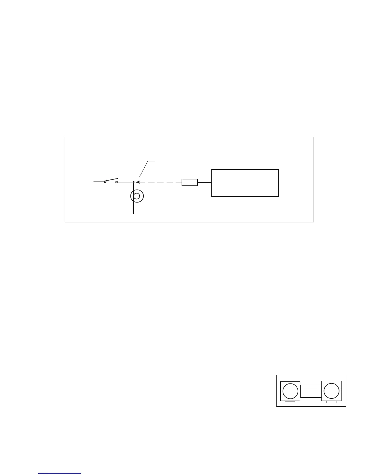
Tap into the switched side of the Light
Gear or Unsafe
Light
Gear and Unsafe Interface Circuit
Option 3: Use this option to display only the Left and Right Main Gears (no Nose Gear) from a single
input. Connect the Left or Right Main Gear to the EDC as shown below. Select “Gear Main” for the probe in
Configuration Screen #1. This option requires one EDC input. The EDC interface circuit is shown below.
Note: When setting colors, use Green for down and White for up. Red will cause an error.
Gear Up Warning: To provide a Gear Warning the MVP must monitor Gear Position, Airspeed and
Manifold pressure. A voice warning is activated on the following logic:
(Any Gear is up -OR- the Unsafe Indicator is on) AND Airspeed is less than a set value AND N1 is less than
a set value.
Note: See the “Aircraft Number, Gear Warning and TAS Setup” screen to set values.
2.10 Install the CO Guardian CO Detector (Optional):
Install the CO Guardian 353-201 Remote Mount CO Detector in accordance with the appropriate CO Guardian
installation instructions supplied with the unit. The CO Detector connects to RS232 Port 3 on the MVP.
2.11 Install the Shunt:
An external shunt is a strip of metal, usually mounted on a bakelite base. This metal is made of special alloys to
produce a very small, precise signal when current passes through it. It is not affected by temperature changes. If your
aircraft currently has an external shunt you can calibrate your MVP to that shunt. The MVP will match any shunt on
the market.
Install the External Shunt:
The external shunt should be installed in the starter-generator circuit and in an appropriate location
that minimizes the routing of main cables. It should also be mounted in
a location where inadvertent damage cannot occur. If the shunt can be
accessed easily, it should be covered. When mounting the shunt, use self-
locking or safety-wired nuts.
The signal wires from the shunt to the EDC must be fused a short distance
after they leave the shunt. If this is a new installation, install two in-line one-
amp fuses in each of the signal lines from the shunt to the EDC Amp Input.
Note: If you are replacing an existing ammeter, the shunt may already be mounted in the aircraft. If you
already have a shunt installed and know the value of the existing shunt, the MVP can be calibrated to that
shunt.
Shunt
16

 Loading...

