4.9 Connect the MVP "Transmit Lockout Input" pin to the Transmit Key (Optional):
Pulling the MVP Transmit Lockout Input pin to ground freezes the displayed values for the various functions. This
eliminates jumpy readings during transmit. In most (if not all) cases, the MVP “Transmit Lockout Input" does not
need to be connected. If transmit lockout is required, attach the appropriate pin (see the “Working with Connectors”
section of this manual for more information) to a 20 gauge wire. Install the wire with pin into position 3 of the MVP
connector. Route and attach this wire to the transmit key.
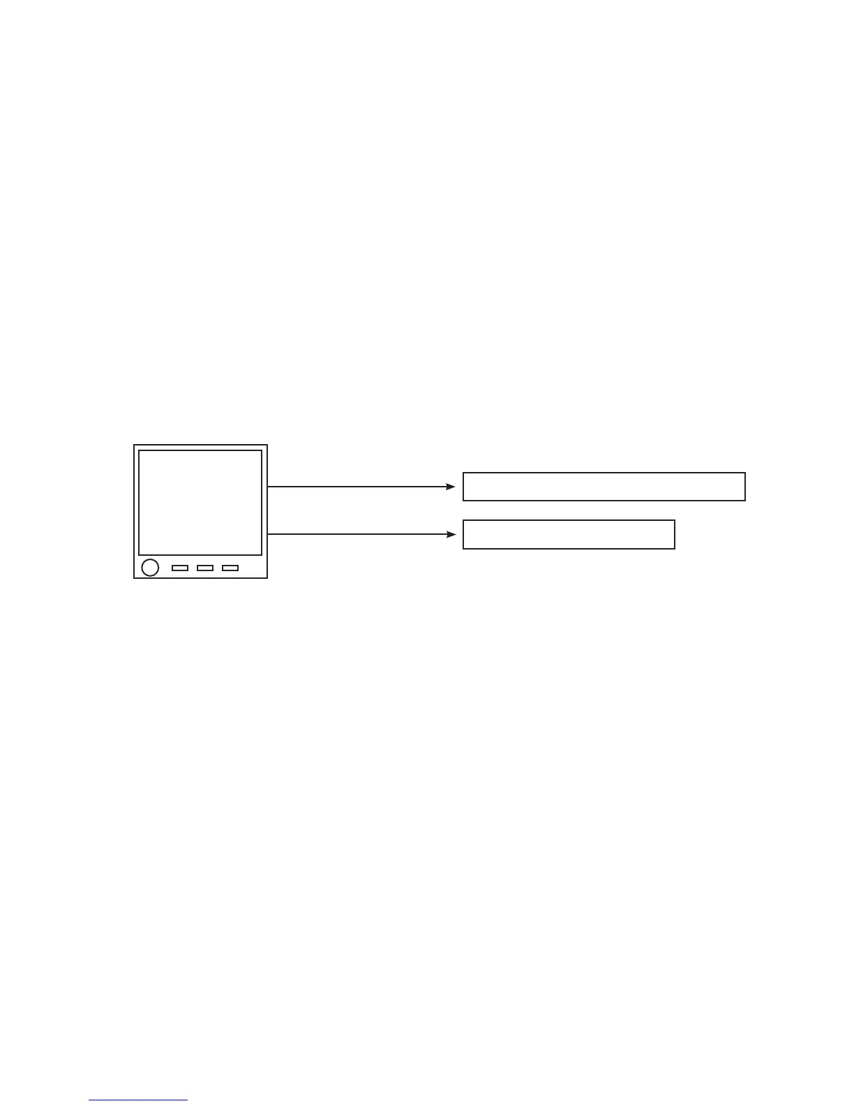
4.10 Connect the MVP Harness to Power and Ground:
Route the power wire (red) to the main bus via a 5-amp Circuit Breaker. Route the ground wire (black) to the aircraft
ground.
WARNING: The power wire is RED and is connected to pin 1 and 2 on the MVP. If aircraft power is
connected to any pin on the MVP other than pin 1 and 2, damage to the MVP and any connected hardware
may occur. Ensure power is provided on pin 1 and 2 of the MVP before attaching the connector.
4.11 Connect the MVP Harness to the CO-Guardian CO Detector (Optional):
If a CO detector was installed, connect the RS232 output from the Remote Mounted 353-201 (experimental only)
or 452-201-011 (certified) CO Detector to Pin 11 (Port 3 In) on the MVP. Refer to CO-Guardian’s installation
instructions for further information on the CO Detector.
Note: The CO Detector shares the same port on the MVP as the second EDC. If the CO Detector is installed, a second
EDC cannot be installed.
4.12 Connect to the MVP RTDO Port (Optional):
The RTDO (Real Time Data Out) port provides a method for interfacing the MVP-50T to external devices. This port
is isolated for the operation of the MVP and its system components. If this port is to be used, connect it to the external
device at this time.
MVP
Power & Ground
Power (Red, Pin 1&2)
To Main Bus via 5-amp Breaker
Gnd (Black, Pin 14&15)
To Aircraft Ground
35

 Loading...

