When routing the MVP wire harness refer to the "MVP-50 25-pin D-Sub Connector Wiring Diagram" found at the
back of this manual. Ensure no wires obstruct the freedom of travel of any controls.
4.1 Attach the MVP 25-pin D-sub Connector to the MVP:
Secure the connector using the supplied mounting screws.
4.2 Connect the EDC RS422 Wires to the MVP RS422 Wires:
Route the EDC RS422 wires to the back of the MVP Display, cut the wires to length and connect them to the
appropriate MVP RS422 wires.
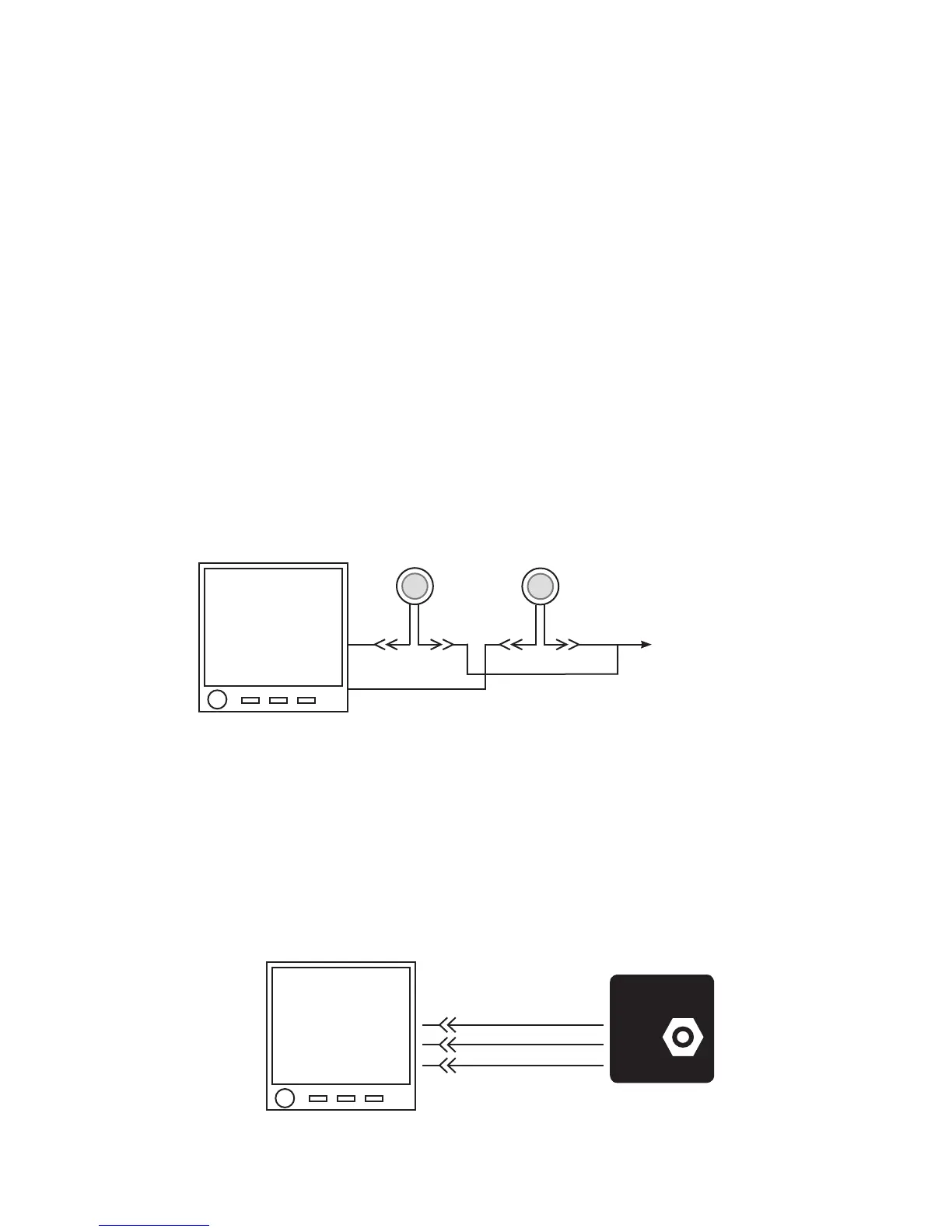
4.3 Connect the MVP Harness to the Master Warning and Caution Lights (Optional):
If the Warning and Caution Lights are installed, route the MVP Master Warning Out wire (White/Yellow, Pin 16)
to the Master Warning (Red) Light (AL-1R) White/Yellow wire, cut the wires to length, install the appropriate
connectors (see the “Working with Connectors” section of this manual for more information) and connect to the
AL-1R.
Route the MVP Master Caution Out wire (White/Yellow, Pin 17) to the Master Caution (Yellow) Light (AL-1Y)
White/Yellow wire, cut the wires to length, install the appropriate connectors (see the “Working with Connectors”
section of this manual for more information) and connect to the AL-1Y.
4.4 Connect the MVP Harness to the Voice Alarm Control Panel (AV-17CP) (Optional):
If the voice alarms provided by the MVP are to be used, route the three MVP Voice Control wires to the AV-17CP, cut
the wires to length, install the appropriate connectors (see the “Working with Connectors” section of this manual for
more information) and connect to the AV-17CP.
To MVP/EDC
5-amp Circuit
Breaker
Pin 16
Wht/Yel Red
Wht/Yel Red
Pin 17
Red
Yel
MVP
Voice Control
Inputs
White/Brown
White/Red
White/Orange
(OFF)
(ACK)
(+5V)
20
21
22
voice alarm
ack
on
off
Control Panel
33

 Loading...

