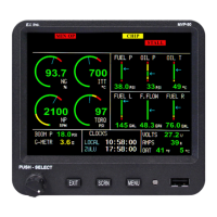
Troubleshooting the MVP system can be relatively simple. First the MVP must be powered-up. This requires only a
power and ground connection to the MVP. Next the EDC needs to be powered-up and communicating with the MVP.
Power and ground are supplied to the EDC on two wires and the EDC communicates with the MVP on two RS422
wires. A "COM" error will be displayed if the EDC is not communicating with the EDC.
The rest of the system is made up of individual functions performing independently of each other. A problem with
a pressure channel will most likely be found in the connection to the transducer, the wire from the transducer to the
EDC or the EDC connection. This same scenario is true for all the functions. Rarely is there a problem with the EDC
or MVP. In some cases the problem can be in the setup programming of the MVP.
7.1 MVP or EDC Problem:
The MVP and EDC require power and ground to operate. The EDC requires two RS422 wires to communicate with
the MVP. Additionally, the EDC supplies power to the Fuel Flow, Fuel Level, and Pressure Transducers. If these
power wires become shorted, the EDC operation will be affected.
A. Symptom: The MVP does not power up.
1. Problem: The Power or Ground wire is open or not connected properly.
a) Action: Measure the voltage on the power and ground wires. Ohm the ground wire to ground.
Look for a short.
B. Symptom: “COM” is displayed for the digital value for most functions. The EDC is not communicating
with the MVP.
1. Problem: One of the EDC external +5 volt power supplies on the Bottom Connector is shorted to
ground.
a) Action: Remove the Bottom Connector. If the COM error goes away, look for a short on one of
the +5 volt wires.
2. Problem: The Power or Ground wire to the EDC is open or not connected properly.
a) Action: Measure the voltage on the appropriate EDC pins. Ohm the Black ground wire to
ground.
3. Problem: The EDC +10 volt or one of the +5 volt supplies on the Top Connector is shorted to Ground.
a) Action: Measure the +10 volt and +5 volt supplies on the Top Connector. If one of the voltages
is low, use an ohmmeter to nd the problem. If all wires ohm properly (>100 ohms), the Power or
Ground wire to the Top Connector may be open.
4. Problem: One of the RS422 wires from the EDC to the MVP may be open or reversed.
a) Action: Inspect the wires. Remove the connectors from the EDC and the MVP and check for
continuity and polarity. Reverse the wires and see if this xes the problem. This will not damage the
EDC or the MVP.
C. Symptom: “REF” is displayed for the digital value for all temperature functions.
1. Problem: The Middle Connector on the EDC is loose or not connected. The Reference Diode on pin
10 and 28 of the EDC Middle Connector is damaged. Note: Pin 28 should measure 0 volts and pin 10
should measure around .6 volts.
53

 Loading...