29
Instruction Manual
PS 8000 DT Series
EN
Date: 04-22-2011
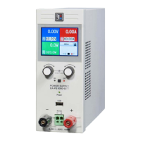
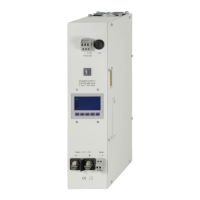
About the device
3.2 Legend
A - Power switch
B - Control panel
C - Power output
D - Analogue interface, 15pole, female
E - Slot for digital extension cards
F - System Bus
G - Fan
H - Input fuse (for value see section “2.2 Technical
specications”)
J - Power input socket, 3pole, IEC 60320
3.3 Scopeofdelivery
1 x Power supply unit
1 x Printed user manual
1 x Mains cord
1 x Plug for System Bus
4. General
4.1 Prologue/Warning
This instruction manual and the device are intended to be used
by users who know about the principle of a power supply. The
handling of the device should not be left to persons who are
unaware of the basic terms of electrotechnology, because these
are not described in this manual. Inappropriate handling and
non-observance to the safety instructions may lead to a damage
of the device or loss of warranty!
4.2 Cooling
The air inlets on the bottom and the air outlet on the rear have
to be kept clean to ensure proper cooling. Take care of at least
10cm distance at the rear to any surrounding objects in order
to guarantee unimpeded air ow.
4.3 Openingthedevice
When opening the unit or removing parts from the inside with
tools there is risk of electric shock by dangerous voltages.
Open the unit only at your own risk and disconnect it from the
mains before.
Any servicing or repair may only be carried out by trained
personnel, which is instructed about the hazards of electrical
current.
5. Installation
5.1 Visualcheck
After receipt, the unit has to be checked for signs of physical
damage. If any damage is found, the unit may not be operated.
Also contact your dealer immediately.
5.2 Mainsconnection
The unit is grounded via the mains cord. Thus the unit may
only be operated at a mains socket with grounding contact.
This must not be interrupted by an extension cable without
ground conductor!
The unit is fused with a 5 x 20mm safety fuse (for value see
technical specs table), which is accessible on the rear.
5.3 DCoutputterminal
The power output is located on the front of the device.
The output is not fused! In order to avoid damage to the load
application, always take care for the nominal values of the load.
The cross section of the load leads depends on several condi-
tions, like the output current, the lead length and the ambient
temperature.
Up to 1.5m lead length we recommend to use:
up to 10A: 0,75mm² up to 15A: 1,5mm²
up to 30A: 4mm² up to 40A: 6mm²
up to 60A: 16mm²
percable (exible wire).
The outputs “+” and “-“ are not grounded, so that one of them
may be grounded if necessary.
Attention!Whengroundingoneoftheoutputpolesalways
checkifoneofthepolesoftheload(eg.electronicload)is
alsogrounded.Thiscouldresultinashort-circuit!
Attention! Watch the potential shift of the output poles
whenusingseriesconnection!Groundingisherebyonly
recommendedatthepolewiththelowestpotentialagainst
ground.
5.4 Terminal„Sense“(Remotesense)
In order to compensate the voltage drop along the load leads
(max. 1V per lead), the power supply can „sense“ the voltage at
the load instead at the output. It will regulate the output voltage
so that the desired voltage is provided to the load.
The connection for remote sense is done at the terminal „Sy-
stemBus“ on the rear side, pins 1 and 2. See section 3.1.
(+)Sensemustonlybeconnectedto(+)attheloadappli-
cationand(–)Sensemustonlybeconnectedto(–)!Else
bothsystemscantakedamage.
For additional information also see section 7.7.
5.5 Interfacecardslot
The unit can be equipped with an optional interface card. The
slot to insert the card is located at the rear side. Further infor-
mation about the interface cards can be found in section “9.
Digital interface cards”.

 Loading...