40
© 2006, Elektro-Automatik GmbH & Co. KG
Irrtümer und Änderungen vorbehalten
EN
Instruction Manual
PS 8000 DT Series
Date: 04-22-2011
Operating the device
There are some restrictions and rules to consider because of
safety and isolation reasons:
• No negative DC output pole of a unit in the series
connectionmayberaisedtoapotential>300Vagainst
ground(PE)!
• TheSharebusmustnotbewired!
• Thegrounds(AGND,DGND)oftheanalogueinterfaces
oftheunitsmustnotbewiredtoeachother!
• Remotesensemustnotbewired!
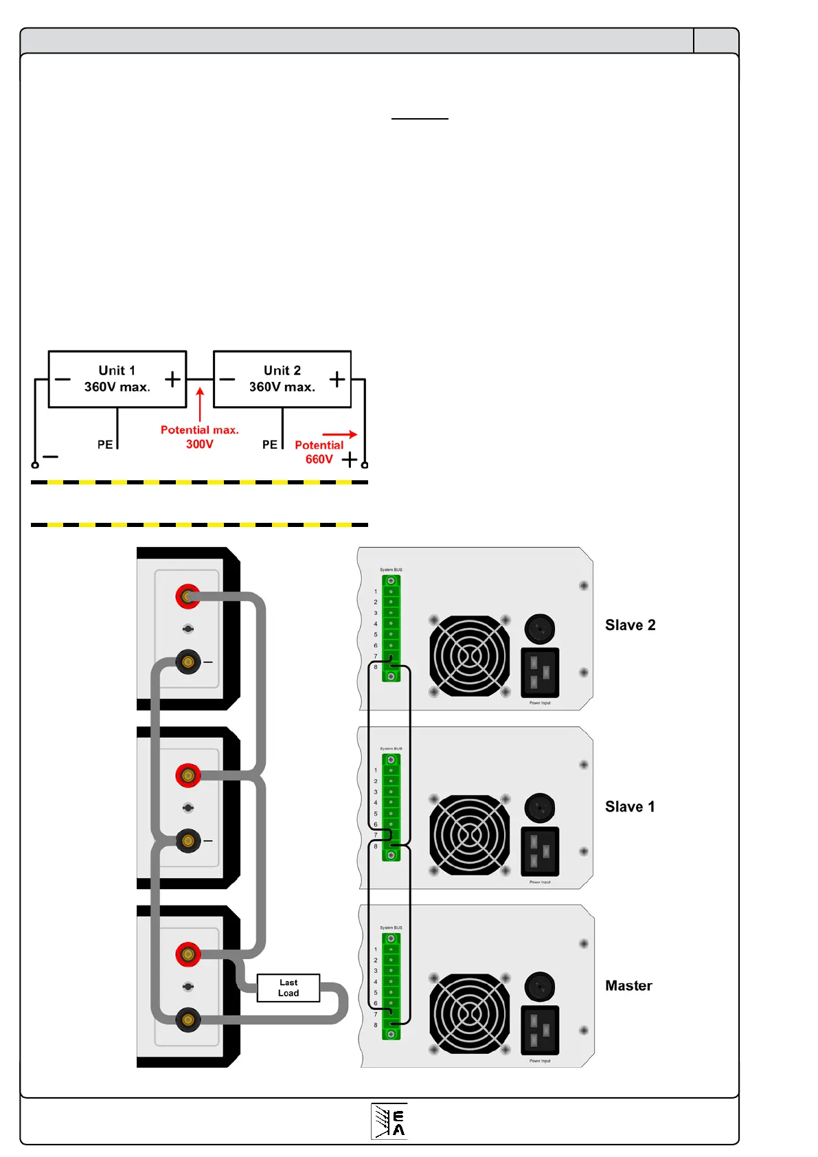
Example: Two identical units with 360V nominal voltage, for
example PSI 8360-10 DT, shall be connected in series. When
calculating, the total voltage of that series connection could go
up to 720V. Looking at the resulting potentials on the negative
outputs of the units, the 2nd unit‘s negative DC pole could be
raised to 360V. This is not permitted! So the lower unit has to
be limited to a certain maximum. The gure below claries that
the resulting total voltage would be 660V:
Caution!Atotalvoltageofaseriesconnectionof600V
shouldnotbeexceeded!
11.3 ParallelconnectioninShareBusmode
Note: only available with devices from 1kW nominal power!
Attention!Onlyunitsofthesametype(voltageandcurrent)
mustbeusedforthisoperationmode.
In order to increase the output current, two or more units of
the same type can be connected in parallel. Always take care
for a sufcient cross section of the load leads! Preferrably, all
leads to the load should be of same length and cross section.
Follwing connections are required: connect all (+) DC outputs
of the units to each other and all (–) DC outputs to each other.
Pin 7 (Share Bus) and pin 8 (Ground) of terminal SystemBus
of all units are also connected in parallel. In case remote sense
is also required, all Sense+ and all Sense - inputs are connected
in parallel and also with the load.
It is recommended to dene one unit as master that controls
voltage and current of the system. At any slave the set values of
voltage, current and power (if available) should be set to 100%.
All units displays their actual values, there will be no totals
formation of the system output current.
In order to control the whole system remotely, it is sufcient to
control the master via its analogue or digital interface. When
reading actual values, the voltage monitor value will represent
the overall system voltage, but the current monitor only the
output current of the master. In order to get accurate readings,
either the actual current is multiplied by the number of units in
the parallel connection (only applicable if all have the same no-
minal output current) or all units will have to be read seperately.
For an example wiring see gure 9.
Figure 9. Parallel connection with Share Bus
 Loading...