30
© 2006, Elektro-Automatik GmbH & Co. KG
Irrtümer und Änderungen vorbehalten
EN
Instruction Manual
PS 8000 DT Series
Date: 04-22-2011
6. Handling
6.1 Thedisplay
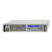
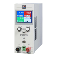
Figure 4 depicts an overview of the dot matrix display and the
control panel. During normal operation, the display areas show
the actual values of voltage (left side) and current (right side)
and device status (middle). In preset mode, the left display
area shows the set values of voltage (Preset Voltage), of the
overvoltage protection threshold (Preset OVP) or the under-
voltage limit (Preset UVL). The right display area shows the
set values of current (Preset Current) or power (Preset Power,
only models from 1kW). In the device setup the display is used
to show adjustable parameters and settings.
The status area in the middle can show following status:
CV - Constant voltage regulation (only when output is „on“)
OT - Overtemperature error
OVP - Overvoltage error
CC - Constant current regulation (only when output is „on“)
CP - Constant power regulation (only when output is „on“)
Fine- Fine adjustment for both rotary knobs active
Legend:
1 - Left display area: Actual voltage or set value U, UVL, OVP
2 - Status area: status display like CC, CV etc.
3 - Right display area: Actual current or set value I, P
4 - Control buttons: Setting the device condition etc.
5 - Rotary knob right: Set value adjustment of I and P, as well
as settings in the device setup
6 - Preset buttons: Switching to set value display
7 - Rotary knob left: Set value adjustment of U, UVL, OVP, as
well as parameters in the device setup
About the device
Figure 4. Control panel
6.2 Pushbuttonsonthecontrolpanel
Pushbutton PresetVoltage
During normal operation the button is used to switch the display
from actual to preset value of the output voltage (preset mode).
The left display area will then show like this:
In preset mode, the left rotary knob (Voltage/UVL/OVP) is
used to adjust the voltage set value the same way as during
normal operation from 0...100% U
Nom
. The adjusted value is
instantly transferred to the output!
Attention! The set value adjustment can be limited by the
undervoltage threshold UVL. See below.
A second push exits the preset mode instantly or it is exited
automatically after 5s, if no preset button is pushed or any set
value is altered.
During remote control by analogue or digital interface the preset
mode can be used to check the voltage set value that is given
from remote.
The button may be locked by the condition LOCK.See below.
In memory selection mode the button is also used to switch to
the voltage set value of the selected memory set, but in this
mode the set value is not transferred to the output. The left
display area will then show like this:

 Loading...
