35
Instruction Manual
PS 8000 DT Series
EN
Date: 04-22-2011
Operating the device
7.7 Remotesenseisactive
Remote sense operation is used to compensate voltage drops
along the leads between the power supply and the load. Becau-
se this is limited to a certain level, it is recommended to match
the cross section of the load leads to the output current and
thus minimise the voltage drop.
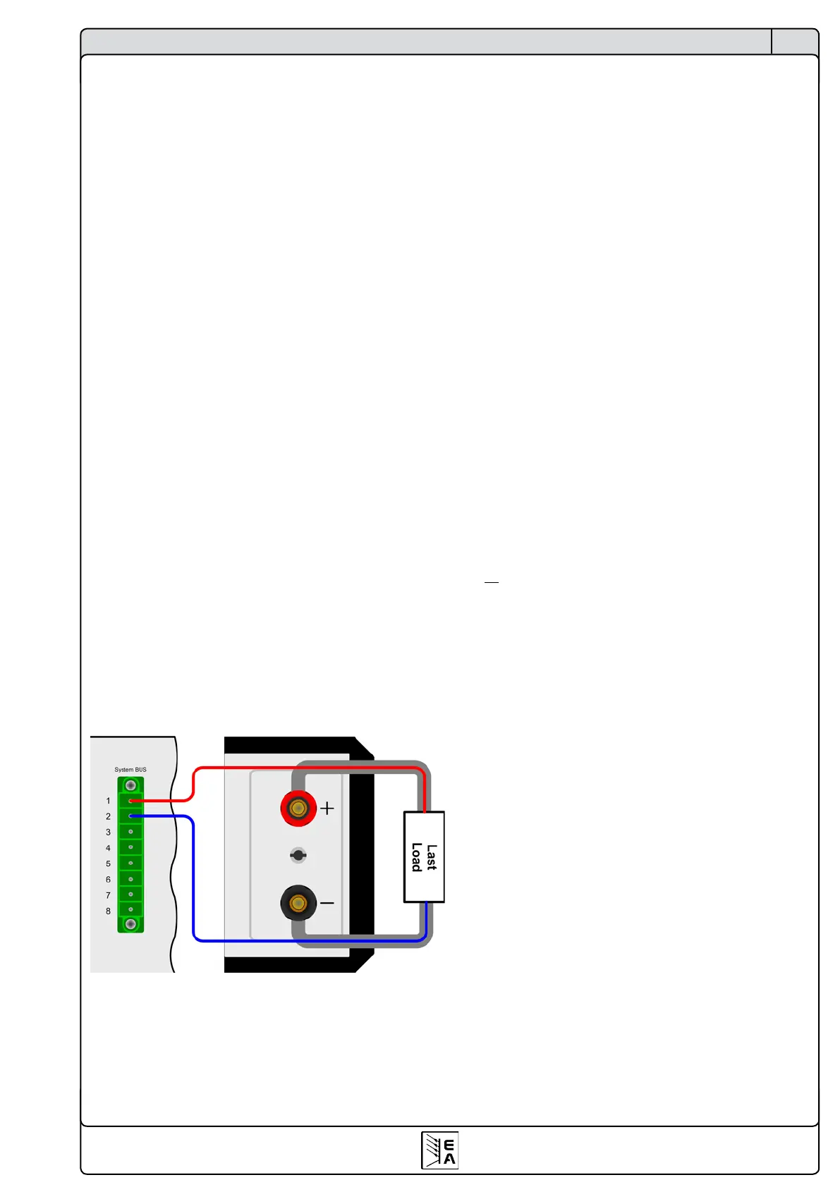
The sense input is located on the rear, at terminal System
Bus, where the sense leads are connected to the load with
correct polarity. The power supply will detect the external sense
automatically and compensate the output voltage by the actual
voltage at the load instead of the output. The output voltage
will be raised by the value of the voltage drop between power
supply and load.
Maximum compensation: 1V per lead.
Also see gure 5 below.
7.8 Mainsundervoltageorovervoltageoccurs
The device features an active rectication with PFC and a wide
range input. This means, it can be operated at input voltages of
approx. 90V...264V. Input voltages below 90V are considered
as blackout, respectively as complete switch-off and will store
the last condition, as well as switch off the power output.
Permanent input undervoltage or overvoltage must be
avoided!
Important! Models with 1500W nominal power will derate
the output power down to 1000W at input voltages below
approx.150V.
7.9 Connectingdifferenttypesofloads
Different types of loads, such as ohmic loads (lamp, resistor),
electronic loads or inductive loads (motor) behave differently
and can retroact to the power supply. For example, motors
can induce a countervoltage which may cause the overvoltage
protection of the power supply to shut off the output.
Electronic loads have regulator circuits for voltage, current and
power that can counteract to the ones of the power supply and
may result in increased output ripple or other, unwanted side
effects. Ohmic loads are almost 100% neutral. It is recommen-
ded to consider the load situation when planning applications.
8. Devicesetup
The device setup is intended to set parameters that are not
constantly altered. Three elementary settings are always avai-
lable, other settings only if a digital interface card is equipped.
The device setup can be accessed while the output is switched
off and by pressing both pushbuttons of the rotary knobs (see
section 6.3) simultaneously >2s. Leaving the setup and storing
the settings is done the same way.
All digital interface specic settings remain unmodied when
inserting a different card. Thereby, the user don‘t has to setup
the interface cards everytime the type changes.
Following elementarysettingsare available:
Name: AutoPwrOn Default: on
Settings: on, off
Meaning: „Auto Power On“, if set to „on“ it activates the resto-
ration of the last output state when the device was switched off
or when a blackout occured. This is intended to be used in case
the power supply is supposed to continue working as soon as
it is powered again. With „off“ the output remains switched off.
Name: AI range Default: 0-10
Settings: 0-5, 0-10
Meaning: selects the control voltage range to use with the
analogue interface.
Name: Contrast Default: 70
Settings: 50...100
Adjusts the contrast of the LCD display.
For all interface cards this setting applies:
Name: Device node Default: 1
Settings: 1...30
Meaning: Selects the device‘s address (device node is taken
from the CAN terminology). When using the device on a bus sy-
stem (CAN or GPIB), every device must have a unique address!
Following settings only with CANinterfaceIF-C1:
Name: Baud Default: 100k
Settings: 10k, 25k, 50k, 100k, 125k, 250k,
500k, 1M
Meaning: Selects the CAN transmission baud rate or Megabaud.
Name: RID Default: 0
Settings: 0...31
Meaning: Selects the relocatable identier segment (RID). Refer
to CAN terminology or instruction manual of the IF-C1 CAN
interface card for further information.
Name: Bus term Default: on
Settings: on, off
Meaning: activates/deactives the bus termination resistor of
the CAN interface card. This is required if the device is at the
end of the bus.
Figure 5. Wiring the sense

 Loading...