36
© 2006, Elektro-Automatik GmbH & Co. KG
Irrtümer und Änderungen vorbehalten
EN
Instruction Manual
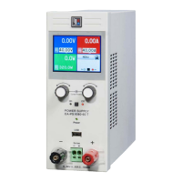
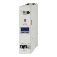
PS 8000 DT Series
Date: 04-22-2011
Following settings only with RS232interfaceIF-R1:
Name: Baud
Default
: 57600
Settings
: 9600, 19200, 38400, 57600
Meaning: Selects the serial transmission baudrate in baud.
Further parameters for the RS232 are not congurable, but
dened as follows:
Parity = odd
Stop bits = 1
Data bits = 8
and have to be set to the same conguration at the PC.
Following settings only with ProbusinterfaceIF-PB1:
Name: Profibus
Default
: 1
Settings
: 1-125
Meaning: Dene the Probus address of the device. This
address is used apart from the device node to implement and
access the unit on a eld bus system.
9. Digitalinterfacecards
The device supports following pluggable interface cards:
IF-U1(USB)
IF-R1(RS232)
IF-C1(CAN)
IF-G1(GPIB/IEEE)
IF-E1(Ethernet/LAN+USB)
IF-PB1(Probus)
The cards require only a little or no setup after insertion. The
card specic settings are kept, even if the card is replaced by
one of different type. Thereby it is not necessary to congure
the card settings everytime a card is inserted.
Details about the technical specs of the interface cards and the
handling, as well as instructions to implement the device into a
bus system or to control the device by means of a PC (LabView
etc.) can be found in the user manual for the IF cards.
Important!Insertionorremovalonlyifthedeviceiscompletely
switchedoff(powerswitch)!
About conguration of the plugged cards see section “8. Device
setup”.
Operating the device
10. Analogueinterface
10.1 General
The integrated, 15 pole analogue interface is located on the
front and offers, amongst others, following possibilities:
• Remote control of output voltage and current
• Remote control of output power (only models from 1kW)
• Remote monitoring of status (OT, OVP, CC, CV)
• Remote monitoring of actual values
• Remotely switching the output on/off
The control voltage range that is going to be used is selected in
the device setup. See section “8. Device setup”. The reference
voltage at output pin 3 is related to the chosen setting and will
be either 5V or 10V.
Usage instructions:
• Controlling the device with analogue voltages requires to
switch it to remote control with pin „REMOTE“ (5).
• Before connecting the application that is used to control the
power supply, make sure to wire all leads correctly and check
if the application is unable to put in voltages higher than
specied (max. 12V).
• The input REM-SB (remote standby, pin 13) overrides the
pushbutton Output On. It means, the output can not be
switched on by the button if the pin denes the output state
as „off“ So it can be as emergency power off.
• The output VREF can be used to build set values for the set
value inputs VSEL, CSEL and PSEL. For example, if only
current control is required, pin VSEL and PSEL can be bridged
to VREF. CSEL is then either fed by an external voltage (0...5V
or 0...10V) or via a potentiometer between VREF and ground.
Also see next section.
• Putting in set values up to 10V while the 0...5V range is
selected will ignore any voltage above 5V (clipping) and keep
the output value at 100%.
• The grounds of the analogue interface are related to
minusoutput.

 Loading...