Resistance Welder MULTISPOT MI-100
Design and functionality
20
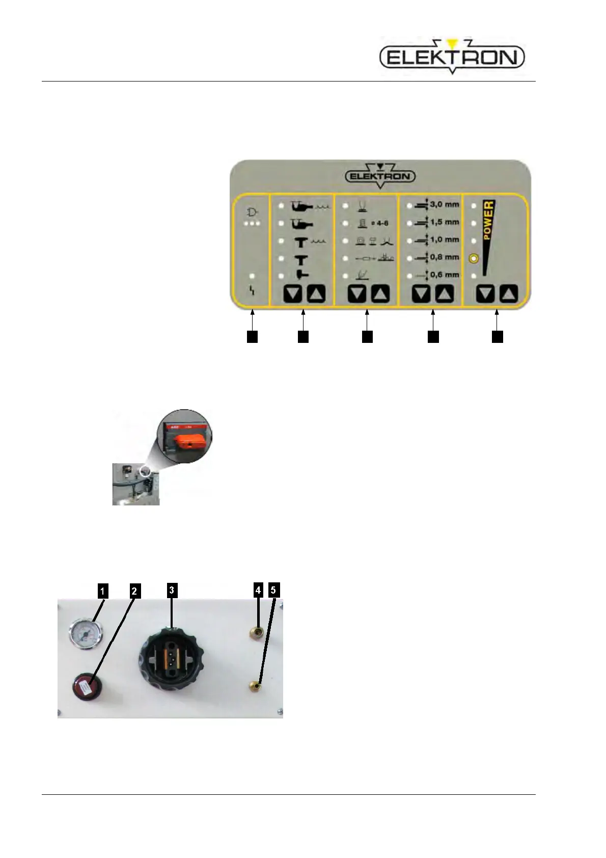
4.3 Display and control elements
4.3.1 On the display and control panel
1 LED “malfunction” → see also
7.2.1
2 Touch key for selecting welding
tool
3 Touch key for selecting welding
gun functions
4 Touch key for selecting sheet
gauges
5 Touch key for power selection
1 2 3 4 5
Fig. 11: Display and control panel
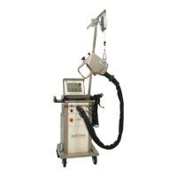
4.3.2 On the inverter control unit
Fig. 12: Power switch (in “OFF” position)
The power switch (Fig. 12) is for switching the power
supply on and off.
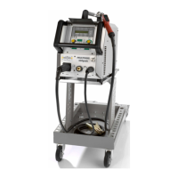
4.4 Connections
4.4.1 Connections on the front side
Fig. 13: Connections on the front side
1 Pressure gauge
displays input pressure.
2 Pressure reducer
continuous adjustment of input pressure
3 Central connection point for weld current,
compressed air and control voltage of the
welding pliers
4 Coolant outlet
5 Coolant return