RGF 300
18/53
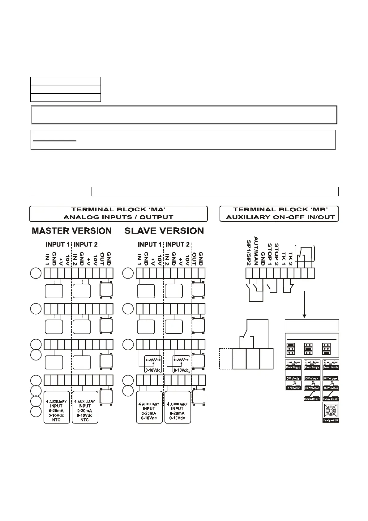
2.2 ELECTRICAL CONNECTIONS, ANALOGUE INPUT SIGNALS
The connections for the control analogue inputs are described below.
They can be connected to the
MA
terminal board, in particular:
MASTER
version Active sensors with control in current (
mA
) or voltage (
Vdc
)
MASTER
version
NTC
sensors with control in
°C
(
10 kohm @ 25 °C
)
SLAVE
version Control signals in current (
mA
) or voltage (
Vdc
)
By connecting the second sensor it is possible to obtain regulation control on the basis of the
G
REATER
SIGNAL VALUE
(STANDARD version) provided by one of the two sensors.
Warning :
when two active type sensors with current or voltage output are connected, use the +V
terminal for supply to
+22 Vdc / 40mA
(
MA 3
for
IN 1
and
MA 7
for
IN 2
)
There is also a control output available on the terminal board to pilot the
rgf
unit, single phase or three
phase, that executes regulation on differentiated loads using the same automatic regulation parameters of the
main
rgf300
.
CONNECTIONS
Trailing cable with rated cross section
1.5 sq mm / 22-14 AWG Cu
fig. 10
4 - 20
mA
4 - 20
mA
1 2 3 4 5 6 7 8 9 10
0 - 10
Vdc
0 - 10
Vdc
1 2 3 4 5 6 7 8 9 10
1 2 3 4 5 6 7 8 9 10
NTC
NTC
0 - 20
mA
0 - 20
mA
1 2 3 4 5 6 7 8 9 10
0-10
Vdc
0-10
Vdc
1 2 3 4 5 6 7 8 9 10
1 2 3 4 5 6 7 8 9 10
1 2 3 4 5 6 7 8 9 10
Alarm
Rela
RL1
NC
S1 S2 TK
NO
COM
1 2 3 4 5 6 7 8 9 10
RGF-MEI
V
M
V
V
M
X
Y
M
V
X
Y
S3
RGF-MEI
10
9
8
RL1
OFF
ALARM - RELAY
NC NA Com
ON 1 ON 2 ON 3
rgf300
ON 2
ON 1
ON 3
ON 2
ON 1
ON 3
ON 2
ON 1
ON 3
rgf300rgf300
GENERAL ALARM
SELECTIONS
1 2 3 4 5 6 7 8 9 10
RGF-MEIRGF-MEI
M
V
SLAVE
SLAVE
SLAVE
SLAVE
SLAVE
SLAVE
SLAVE
SLAVE