RGF 300
19/53
One of the main applications of the
rgf300
series regulators is the control of voltage and speed of rotation of fans. This
is modulated to keep temperature or pressure constant as a work point for one or more refrigerating circuits
(condensator or evaporator mode).
In the
STANDARD
condition, the fan reaches maximum voltage in output (
P4
) coinciding with the work
Set-point
.
Directions are given below for connection or calibration of
rgf300
regulators with
active pressure sensors
,
NTC
temperature sensors and other possible applications for
direct or remote regulation
.
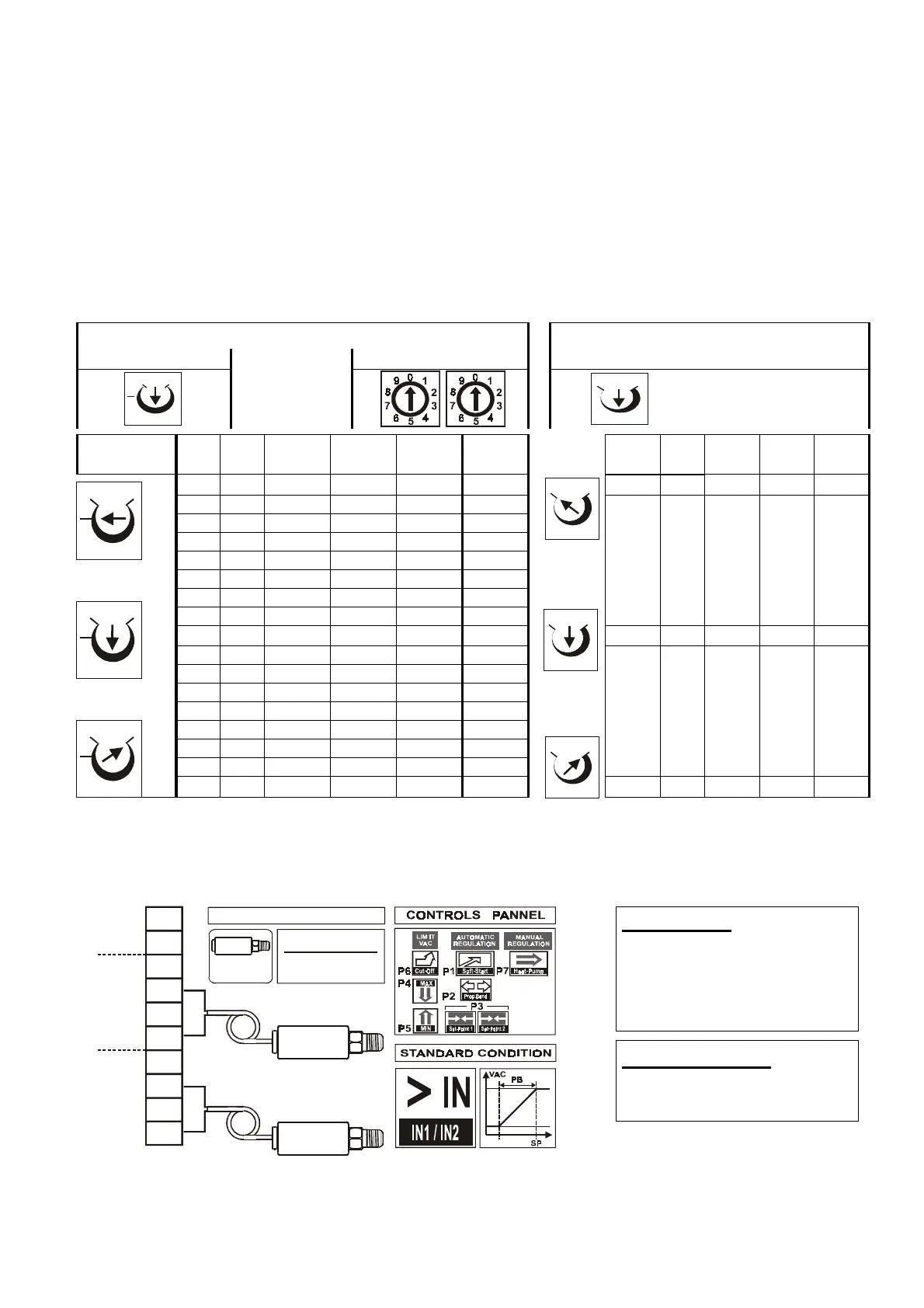
2.2.1 Connection of XSK pressure transducers (4-20 mA)
The table below lists the information necessary for calibration of the
Set-point
(
page 34
) with the position of
P3
referred to the Centesimal Commutators (
Com
.) or Trimmer (
Trim
.), and for calibration of the
Proportional Band
with the position of
P2
.
Set-Point
SP
/
P3 for 4-20mA,
setting
with
SP / P3 Trimmer Centesimal Switch
Proportional Band
PB
/
P2
setting for
4-20 mA pressure transducers
START
position
START
position
Setting
Trimmer
mA V(*)
0-15
bar
0-25
bar
0-30
bar
N°
Set.
Trim
mA
0-15
bar
0-25
bar
0-30
bar
m 4 0.4 0.00 0.00 0.00 00 m 0.4 0.37 0.62 0.75
5 0.5 0.93 01.56 01.87 06
6 0.6 1.87 03.12 03.75 12
7 0.7 2.81 04.68 05.62 18
8 0.8 3.75 06.25 07.50 25
9 0.9 4.69 07.81 09.37 31
10 1.0 5.63 09.37 11.25 37
11 1.1 6.56 10.94 13.12 44
c 12 1.2 7.50 12.50 15.00 50 c 2.1 1.94 3.28 3.93
13 1.3 8.44 14.06 16.87 56
14 1.4 9.38 15.63 18.75 62
15 1.5 10.31 17.19 20.62 68
16 1.6 11.25 18.75 22.50 74
17 1.7 12.19 20.31 24.37 80
18 1.8 13.13 21.88 26.25 87
19 1.9 14.07 23.44 28.12 93
M 20 2.0 15.00 25.00 30.00 99
M 4.0 3.74 6.24 7.50
Tab. 4
(*)
Column
V
gives the voltage values legible with a multimeter (
20Vdc
scale limit) on the
IN
/
Gnd
terminals of the
analogue inputs, corresponding to the
mA
control signal generated by the
4-20mA
transducer in regulation.
Fig. 11
shows the connection of two pressure transducers plus the type of operation (standard) and the operating
regulation controls.
WARNING :
do not invert the transducer
cables (IN / +V) when
connection is made to terminals
1/3 and 5/7 as the transducer
may be damaged.
ATTENTION :
at standard configuration
P3/Set-point
=
max. output fan
fig. 11
10
9
8
7
6
5
4
3
2
1
ACCURACY
PRESSURE TRANSDUCER
GND
OUT
10V
+V
GND
IN 2
10V
+V
GND
IN 1
+/- 3% FS
4-20mA
0-10Vdc
XSK 2
XSK 1
M0
c
m
Mm
c
Mm
c
M
0
c
m
M
0
c
m
M
0
c
m
Mm
c
Mm
c