RGF 300
20/53
2.2.2 Connection of NTC temperature sensors (10kohm @ 25 °C)
Two versions of
NTC
temperature sensors are available for
rgf300
models:
•
X
for scale
+10 °C to +60 °C
•
Y
for scale
- 20 °C to +20 °C
The table below lists the information necessary for calibration of the
Set-point
(
page 34
) with the position of
P3
referred to the centesimal Commutators (
Com
.) or Trimmer (
Trim
.), and for calibration of the
Proportional Band
with the position of
P2
.
Setting of work point SP / Set-point
P3
with NTC probe
Proportional Band PB/P2
SP > Trimmer P3 SP > Centesimal switch with NTC probe
START
position
START
position
START
position
T
RIMMER
SETTING
X (°C)
10°/60°
Y (°C)
-20°/20°
CENTESIMAL
SETTING
N°
X (°C)
10° / 60°
Y (°C)
-20°/ 20°
T
RIMMER
SETTING
For X & Y
Skale
6° -22° 00 10° -20° 3 °C
10 15° -16°
m
20 20° -12°
m
30 25° -8°
40 30° -4°
35° 0° 50 35° 00° 18 °C
c
60 40° 4°
c
70 45° 8°
80 50° 12°
90 55° 16°
M
64° 23°
99 60° 20°
M
30 °C
Tab. 5
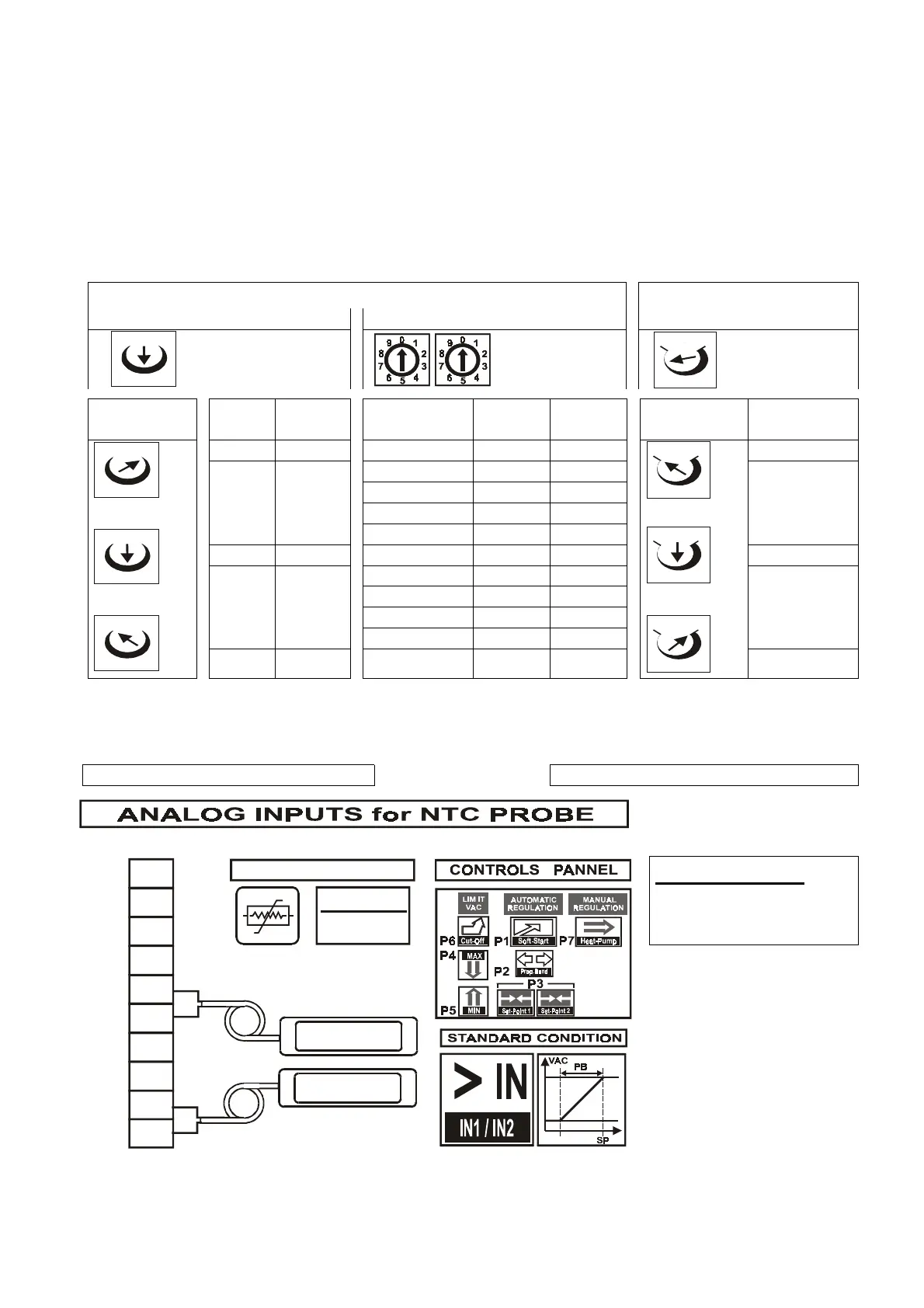
Connection of the two
NTC
sensors is shown in
fig. 12
below.
Also shown is the type of operation (standard) and operating regulation controls.
Master X for scale +10 C° to +60 C° Master Y for scale -20 C° to +20 C°
ATTENTION :
at standard configuration
P3 / Set-point
=
max.
output fan
fig. 12
°C
Airflow = 35"
NO-Air = 70"
T. C.
10
9
8
7
6
5
4
3
2
1
NTC 2
NTC 1
NTC
NTC probe (10 kohm a 25 °C)
GND
OUT
10V
+V
GND
IN 2
10V
+V
GND
IN 1
Mm
c
Mm
c
Mm
c
Mm
c
Mm
c
Mm
c
Mm
c
Mm
c
Mm
c