RGF 300
43/53
5.0 HELPI 10: PORTABLE DISPLAY UNIT
All calibration operations described can easily be carried out with the portable module called
HELP
I
10
for
display of work parameters.
All three phase regulators in the
rgf300
series are fitted with the
CN2
connector located between the
MA
and
MB
terminal boards. After connecting the
HELP
I
10
module, the settings made with the regulator work
parameter trimmers can be chosen and displayed, even if the
rgf300
is being supplied on the workbench.
The portable
HELP
I
10
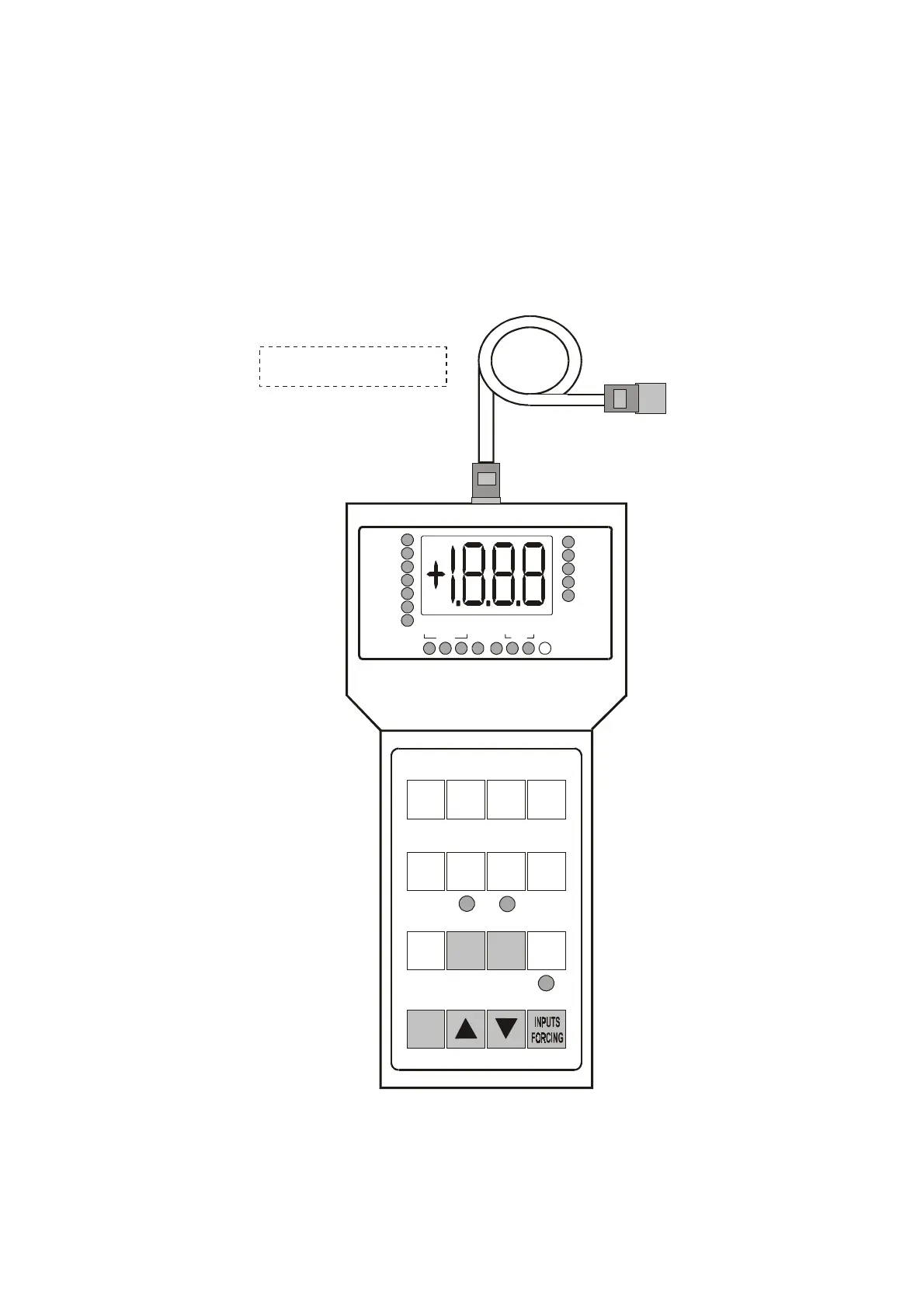
unit is shown in
fig. 39
with function keys described.
fig. 39
1 2 3 4
0-15
bar
4-20
mA
5 6 7 8
9 10 11 12
13 14 15 16
1 - scale 0 / 15 bar
2 - scale 0 / 25 bar
3 - scale 0 / 30 bar
4 - current loop
( 4 - 20 mA )
SP IN 1 IN 2
%C + V
PB
7 - input IN 2
8 - Auxiliary
11 - selection mA mode
REVERSE (-)
12 - Vdc Power supply
for transducers
15 - DOWN arrow
5 - Set-Point
6 - input IN 1
9 - displays the % output
comand
(*) 10/11/13/14/15/16 - push bottons for Proportional Band setting (PB)
rgf SIGNALS'
LED INDICATORS
UNITS OF
MEASUREMENT
LED INDICATORS
Displays the mA values
of INPUT signals
DISPLAYS THE STATUS OF
WORKING PARAMETERS
DIR REV
( + ) ( - )
0-25
bar
0-30
bar
10 - selection °C mode
DIRECT (+)
13 - Proportional Band
14 - UP arrow
16 - push botton for
PB setting
SP
IN 1
IN 2
C/Off
%C
+V
PB
mA
Bar
°C
%
V
0-15 0-25 0-30
BAR
+10 - 20
+60 +20
°C
4-20
mA
0-10
V
CONNECTION CABLE
TERMINAL UNIT / rgf
PREDISPOSITION LED INDICATORS
Cut
Off