RGF 300
44/53
S
UMMARY TABLES FOR USE OF THE
HELP
I
10
DISPLAY MODULE
.
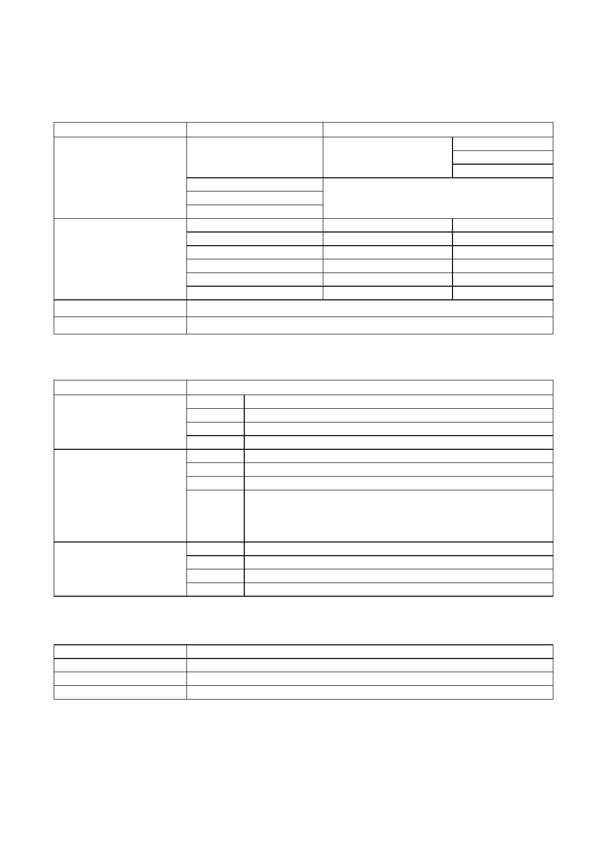
Technical characteristics
Supply voltage
22 V ( 18....36 V ) From the connected appliance
0 - 15 bar
0 - 25 bar
4 - 20 mA
Can be changed via the
keyboard to:
0 - 30 bar
0 - 10V
NTC +10...+60°C
Input
Layouts
NTC -20...+20°C
Main Set-point Units of measurement
mA , V , bar , °C
Transducer input 1 “
mA , V , bar , °C
Transducer input 2 “
mA , V , bar , °C
% output control signal “
% ( 0......100)
Transducer supply voltage “
V
Signals measured
Proportional band “
mA , V , bar , °C
Dimensions
225 x 105 x 40 mm.
Weight
0.5 kg
Screen
N
UMERIC DISPLAY
LCD 3 ½ digit
position left of the display
no. 7
colour green
L
ED
unit
Selected input
function indicates which signal is being displayed at any moment
position below the display
no. 8
colour red
Led unit
Regulator
set-up
function
indicate the set-up on the connected regulator, including units of
measurement and scale limits, for the following signals:
SP , IN1, IN2
.
Also indicates if the scale factor has been modifed from mA to bar
position right of the display
no. 5
colour green
Led unit
Units of measurement
function indicate the units of measurement of the value on the display
Led
Caption Function
DIR (+)
Direct operation selected for calibration of the proportional band
REV(-)
Inverse operation selected for calibration of the proportional band
Inputs Forcing
Forced transducer inputs for calibration of the proportional band