Appendix
Appendix
User's Manual
BAB 740
7—4
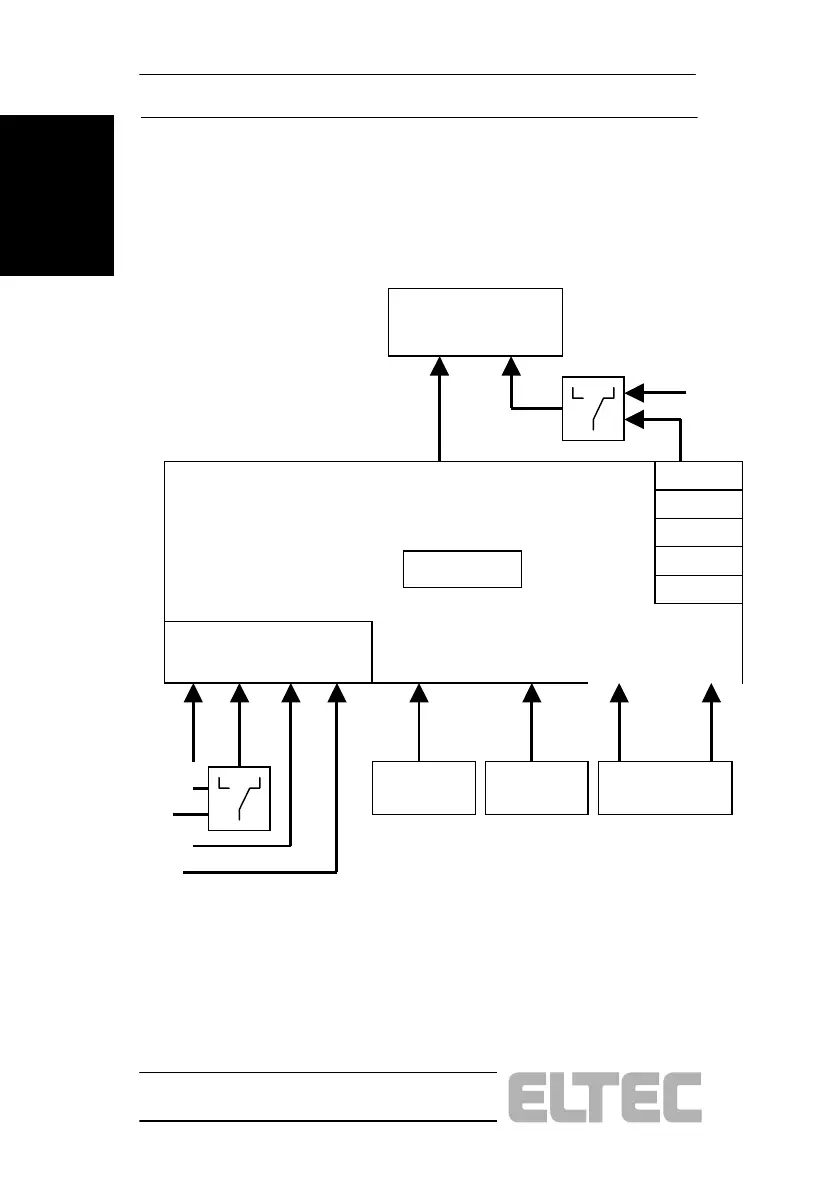
7.1.3 Interrupt Controller
Figure 6: BAB 740 Interrupt Diagram
PowerPC
INT SMI
VME
IDE #0
IDE #1
Timer #0
Timer #1
Timer #2
INT 0
INT OUT
W83C553
PCI
INT A INT B INT C INT D
Super I/O
(PC97307)
...........
INT 1; 3..12; 14; 15 INT 9 INT 5
PMC #1
ESCC
(Z85230)
RTC
(MK48T59)
PMC #2
SCSI
Network
ME
This diagram shows how the on-board interrupt sources are
connected to the interrupt controller, located logically in the
W83C553 chip. This chip then prioritizes and drives the two CPU
interrupt inputs. The priority scheme used is shown below: