14 ESR Series Routers Operation Manual
terminal to factory settings.
Console port RS-232 for local management of the device.
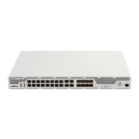
2.4.1.2 ESR-1000 front panel
The front panel layout of the device is depicted in Fig. 2.2.
Fig. 2.2 —ESR-1000 front panel
Table 2.10 lists sizes, LEDs, and controls located on the front panel of the device.
Table 2.10 —Description of connectors, LEDs, and controls located on the front panel
SD memory card installation slot.
USB-enabled devices connection port.
USB-enabled devices connection port.
10G SFP+/ 1G SFP transceivers installation slots.
24 x Gigabit Ethernet 10/100/1000 Base-T (RJ-45) ports.
Current device status indicator.
Device alarm presence and level indicator.
Active VPN sessions indicator.
Data storage activity indicator—SD card or USB Flash
Device failover mode operation indicator.
Backup power supply indicator.
Functional key that reboots the device and resets it to factory settings:
– Pressing the key for less than 10 seconds reboots the device.
– Pressing the key for more than 10 seconds resets the device to
factory settings.
RS-232 console port for local control of the device.

 Loading...