EasyManua.ls Logo

ELTEX ESR-100 - Design

ELTEX ESR-100
109 pages
To Next Page IconTo Next Page
To Previous Page IconTo Previous Page
Loading...
16 ESR Series Routers Operation Manual
2.4.2 ESR-100, ESR-200 design
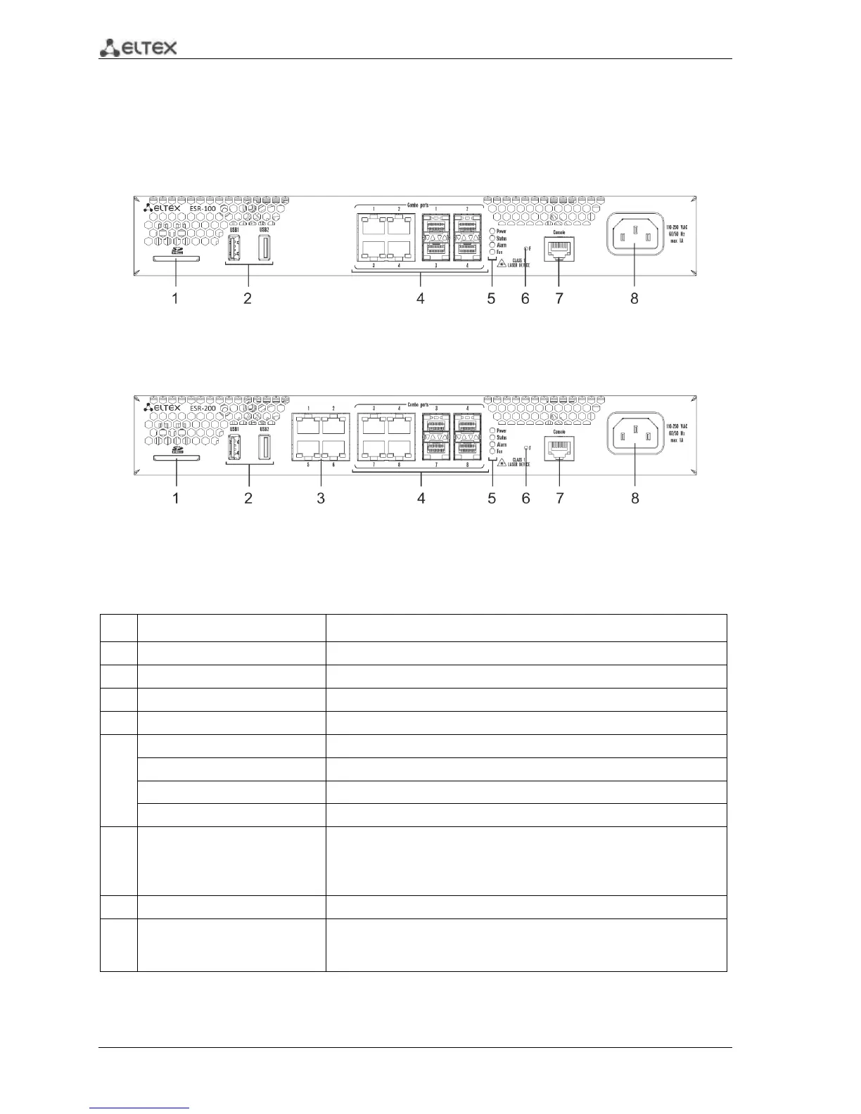
2.4.2.1 ESR-100, ESR-200 front panel
The front panel layout of ESR-100 is depicted in Fig. 2.6.
Fig. 2.6 ESR-100 front panel
The front panel layout of ESR-200 is depicted in Fig. 2.7.
Fig. 2.7 ESR-200 front panel
Table 2.12 lists sizes, LEDs, and controls located on the front panel of ESR-100 and ESR-200 routers.
Table 2.12 Description of connectors, LEDs, and controls located on the front panel
No.
Front panel element
Description
1
SD
SD memory card installation slot.
2
USB1, USB2
2 x USB-enabled devices connection port.
3
[1 .. 4]
4 x Gigabit Ethernet 10/100/1000 Base-T (RJ-45) ports.
4
Combo Ports
4 x Gigabit Ethernet 10/100/1000 Base-X (SFP) ports
5
Power
Device power indicator.
Status
Current device status indicator.
Alarm
Device alarm presence and level indicator.
Fan
Fan alarm indicator.
6
F
Functional key that reboots the device and resets it to factory settings:
Pressing the key for less than 10 seconds reboots the device.
Pressing the key for more than 10 seconds resets the device to
factory settings.
7
Console
RS-232 console port for local control of the device.
8
110-250VAC
60/50Hz
max 1A
Power supply

Table of Contents

Other manuals for ELTEX ESR-100

Related product manuals