ESR Series Routers Operation Manual 15
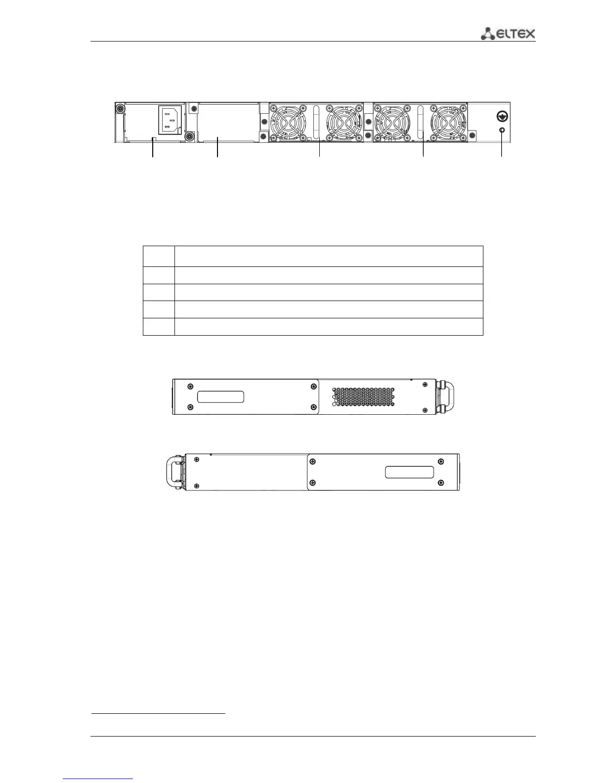
2.4.1.3 ESR-1000, ESR-1200 rear panel
The rear panel layout of ESR-1000, ESR-1200 is depicted in Fig. 2.3
1
.
Fig. 2.3 —ESR-1000, ESR-1200 rear panel
Table 2.11 lists rear panel connectors of the router.
Table 2.11 —Description of rear panel connectors of the router
Backup power supply installation position.
Removable ventilation modules with hot-swapping.
Earth bonding point of the device.
2.4.1.4 Side panels of the device
Fig. 2.4 —The right-side panel of ESR-1000, ESR-1200 routers
Fig. 2.5—The left-side panel of ESR-1000, ESR-1200 routers
Side panels of the device have air vents for heat removal. Do not block air vents. This may cause
components overheating which may result in terminal malfunction. For recommendations on device
installation, see section 'Installation and connection'.
1
The figure shows the router delivery package with a single AC power supply.

 Loading...
