MES1000, MES2000 Ethernet Switches 21
Table 2.11 lists sizes, LEDs and controls located on the front panel MES1124MB, MES2124MB.
Table 2.11 — Description of connectors, LEDs and controls located on the front panel MES1124MB,
MES2124MB
~110-
250VAC,
60/50Hz
max 1A
Connector for AC power supply
~110-
250VAC,
60/50Hz
max 2A
12V battery connection terminals
Indicator of device number in a stack
Stacked device activity mode indicator—master or slave
RS-232 console port for local control of the device
Functional key that reboots the device and resets it to factory settings:
- pressing the key for less than 10 seconds reboots the device.
- pressing the key for more than 10 seconds resets the terminal to factory
settings
24 ports 10/100/100 Base-T (RJ-45)
24 ports 10/100/1000 Base-T (RJ-45)
LED indication of optical interface status
Combo ports: 10/100/1000 Base-T (RJ45) ports and slots for 1000Base-X
Combo transceiver installations
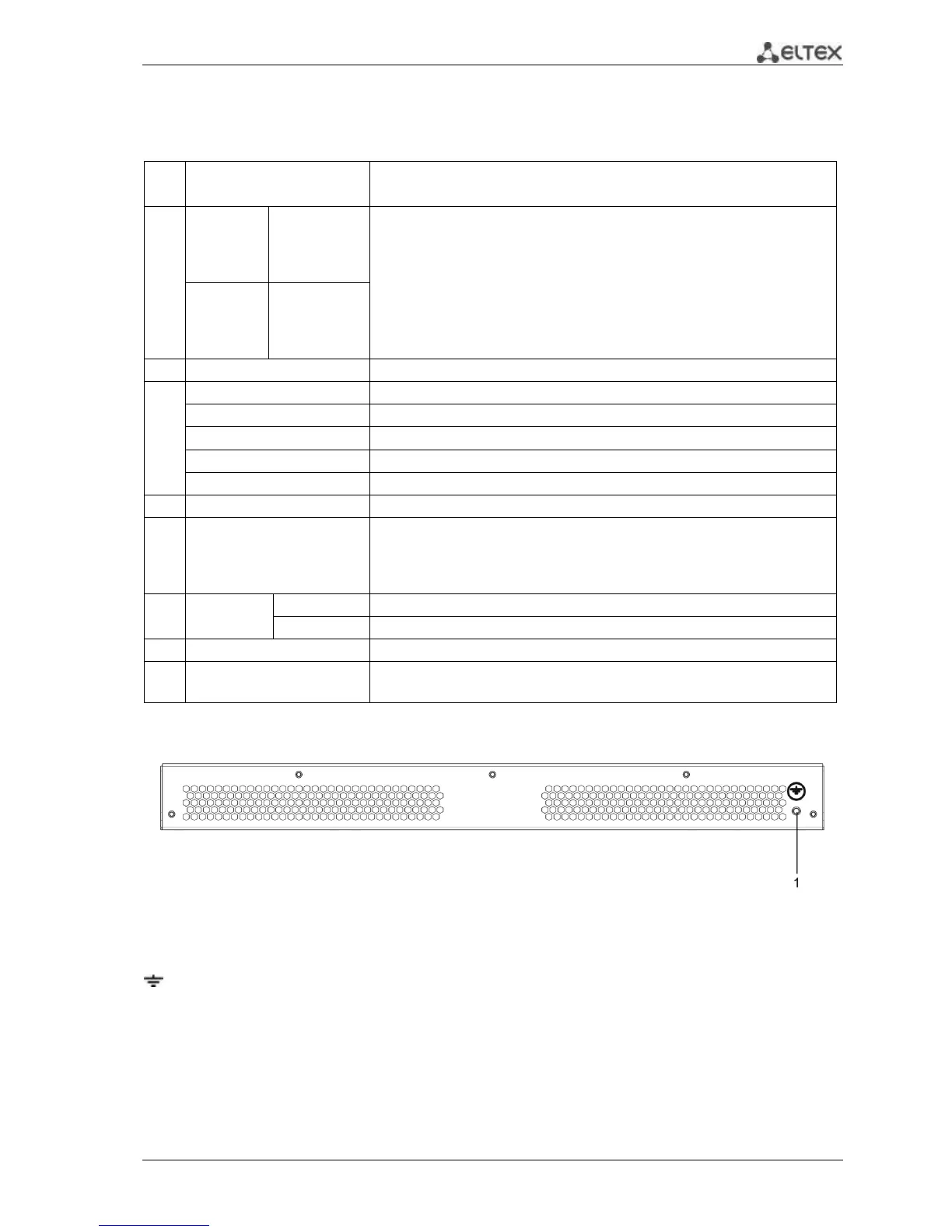
The rear panel layout of MES1124MB, MES2124MB series switches is depicted in Fig. 6.
Fig. 6 – MES1124MB, MES2124MB, rear panel
An earthing bolt is located on the rear panel of MES1124MB, MES2124MB series devices and marked with
(1) symbol.
 Loading...