26 MES1000, MES2000 Ethernet Switches
Table 2.15 —Description of rear panel connectors of the switch
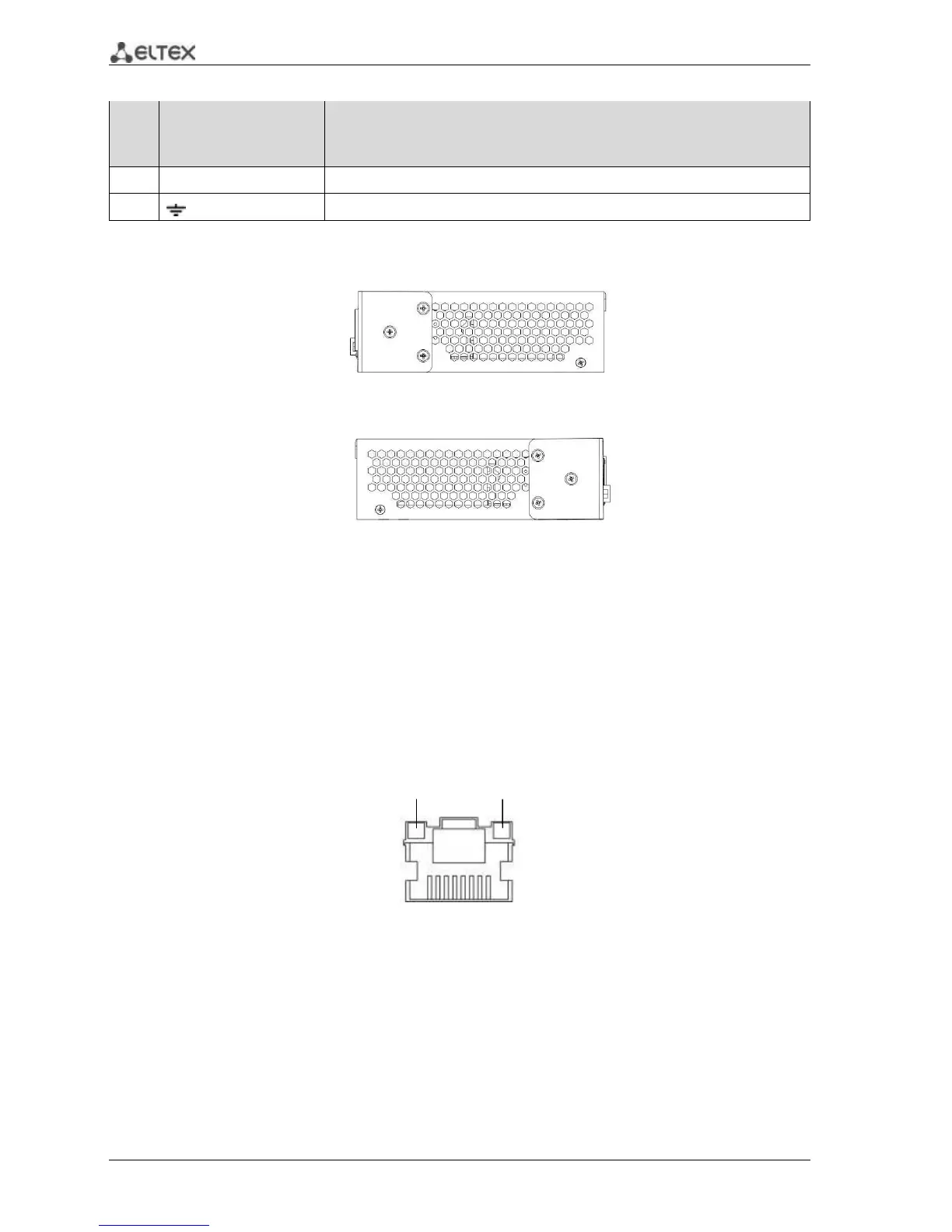
2.4.6 Side panels of the device
Fig. 15—The right-side panel of Ethernet switches
Fig. 16—The left-side panel of Ethernet switches
Side panels of the device have air vents for heat removal. Do not block air vents. This may cause
components overheating which may result in terminal malfunction. For recommendations on device
installation, see section 'Installation and connection'.
2.4.7 Light Indication
Ethernet interface status is represented by two LEDs—amber SPEED and green LINK/ACT—located
next to each interface connector. Location of LEDs is depicted on Fig. 17, 18.
Fig. 17—RJ-45 socket appearance