MES1000, MES2000 Ethernet Switches 27
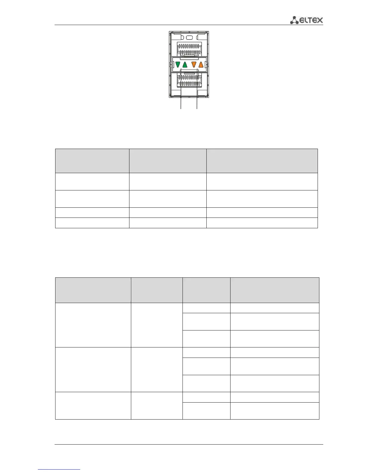
Fig. 18—SFP transceiver socket appearance
Table 2.16 — Ethernet interface status light indication
LINK/ACT indicator is lit
Port is disabled or connection is not
established
10Mbps or 100Mbps connection is
established
1000Mbps connection is established
Data transfer is in progress
Unit ID (1-4) indicators are intended for identifying the number of device in a stack.
System indicators (Power, Master, Fan, RPS) are designed for displaying the operation status of
switches.
Table 2.17 —LED indication of the system indicators
Power is on, normal device
operation
At least one of the secondary power
supply units has failed.
Normal device operation state
Managing or switching device
system failure
Device starts up No IP addresses
assigned to interfaces
Marker of the
master device in a
stack
The device is stack 'master'
The device is not stack 'master' or
stackable mode is not specified