NTU-RG-54xx. User manual (user)
Connectors and controls located on the rear panel of the device are listed in Table 4.
Table 4 – Description of the connectors and controls on the rear panel
# Rear panel element Description
1 On/Off Power button
2 12V Power adapter connector
3 USB Connector for external drives and other USB devices
4 TV RF port for connecting a coaxial cable
5 Phone RJ-11 connector for analogue phone connection
6 LAN 10/100/1000 P1..P4 RJ-11 connector for analogue phone connection
7 Wi-Fi Wi-Fi enabling/disabling button
8 WPS A button which enables automatic secure Wi-Fi connection
9 F A functional key that reboots the device and resets it to factory settings
10 PON SC port (socket) for PON with GPON interface
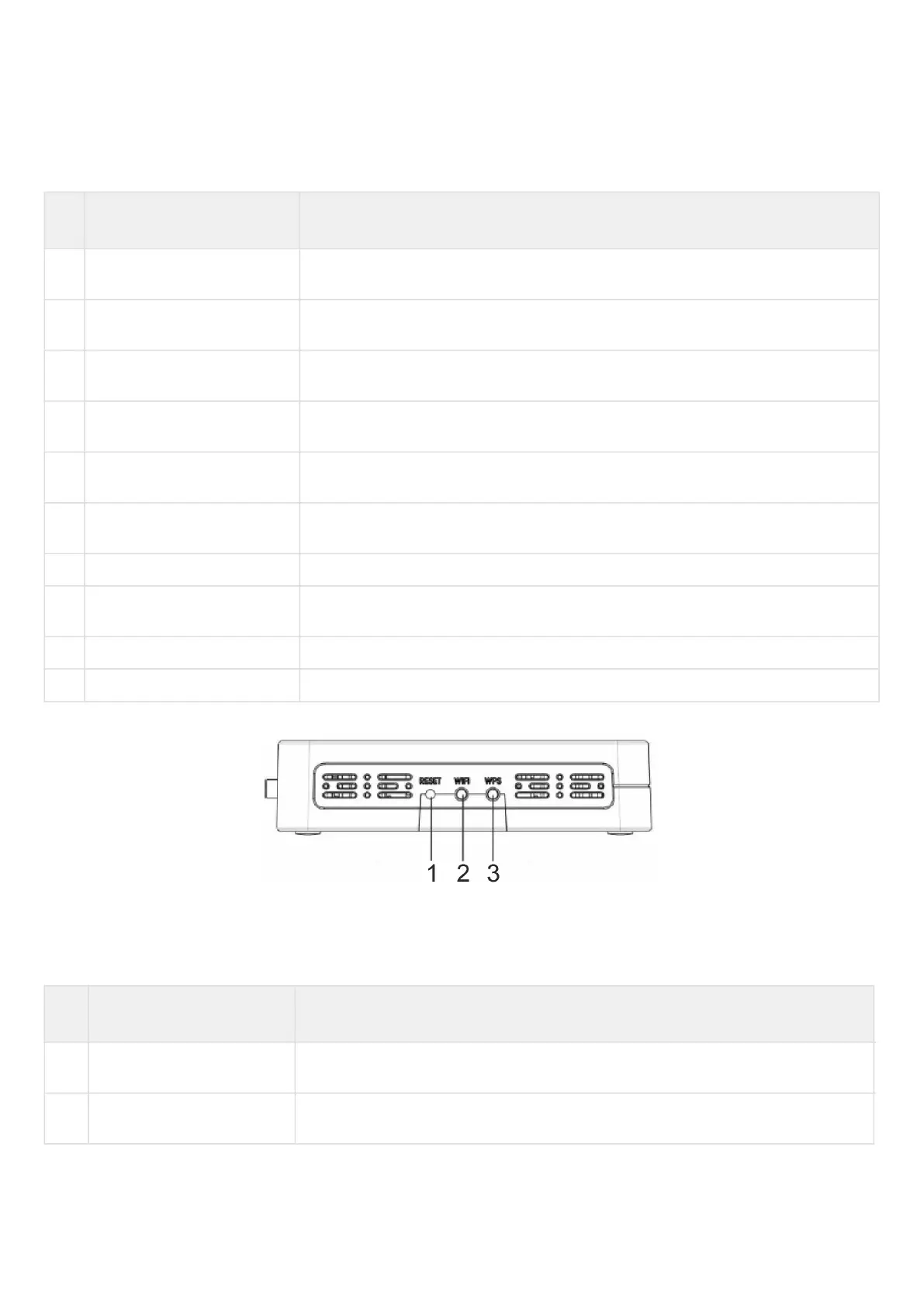
Figure below shows NTU-RG-5402G-W, NTU-RG-5421G-Wac and NTU-RG-5421G-WZ side panel layout.
Figure 6 – NTU-RG-5402G-W, NTU-RG-5421G-Wac and NTU-RG-5421G-WZ side panel layout
See Table 5 for detailed information about buttons located on the side panel of the device.
Table 5 – NTU-RG-5402G-W, NTU-RG-5421G-Wac and NTU-RG-5421G-WZ side panel buttons description
# Side panel element Description
1 Reset A functional key that reboots the device and resets it to factory settings
2 Wi-Fi Wi-Fi enabling/disabling button
 Loading...