Installation
11
All power cables of peripheral devices [computer (2), the printer (4) and the
balance (5)] should be connected to the quad mains power socket (6) as shown in
the figure.
Remark
Before placing balance, PC, display and printer on the desk for connecting their
power cables, the loader should be attached to the analyzer and aligned. Please,
refer to “LOADER installation, service and operation manual” for the instructions on
installation, connection and alignment of the loader.
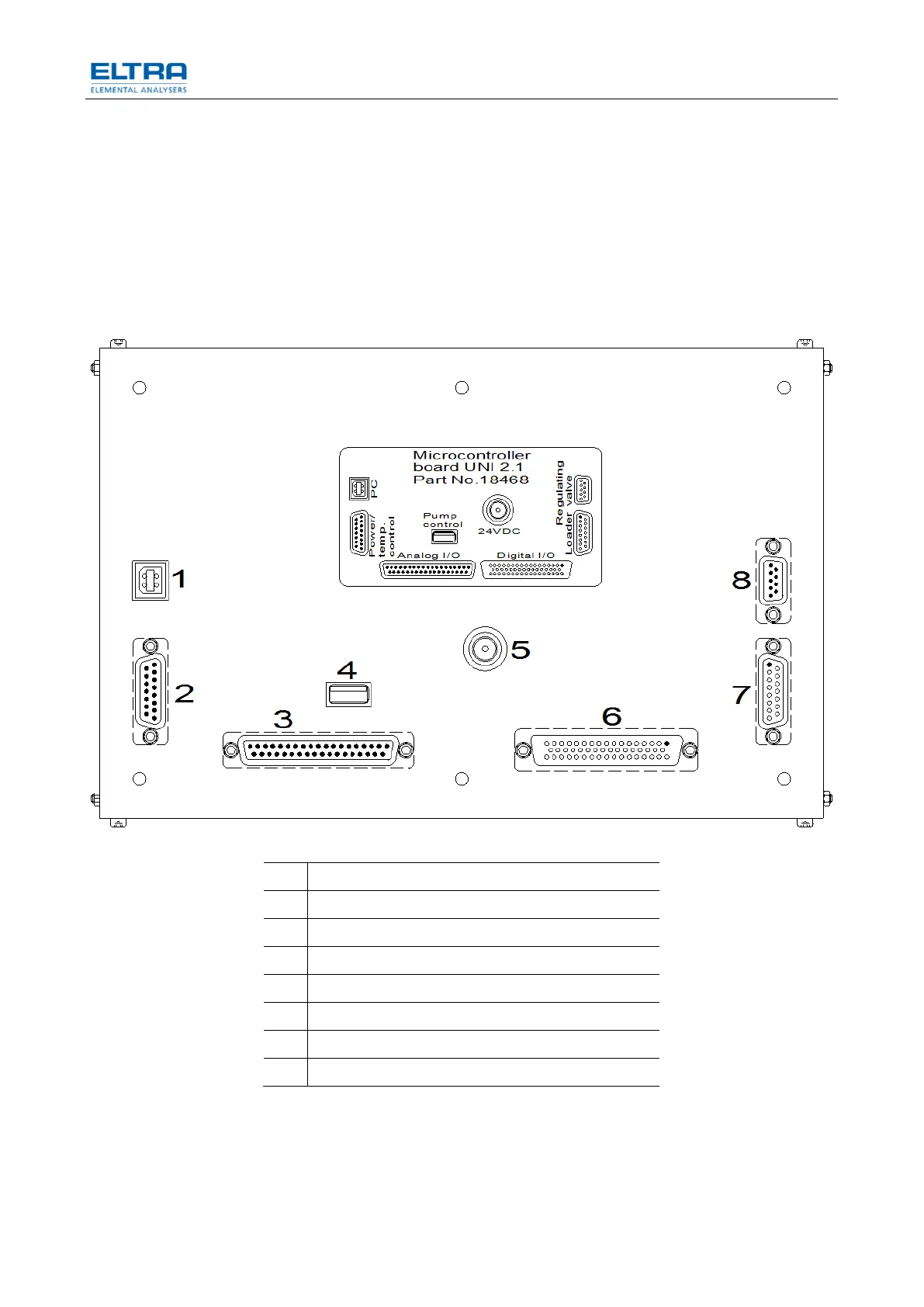
2.4 Data Interface
Fig. 3: Microcontroller board
Power and temperature control interface
Analog input/output signals
Digital input/output signals
Regulating valve (not relevant for CS-580A)
When all units are connected to the mains power, then interface connections can
be made. The required interface cables are included in the scope of supply. The
supplied additional devices have been already adapted to the interfaces when the
analyzers are taken into operation in our company. The plugs are all different from
each other, so that they cannot be interchanged. The computer is already provided
with operation system and with software for controlling the analyzer.

 Loading...


