EM TEST AutoWave
Manual for Operation V 5.9.1 14 / 45
Hardware wiring
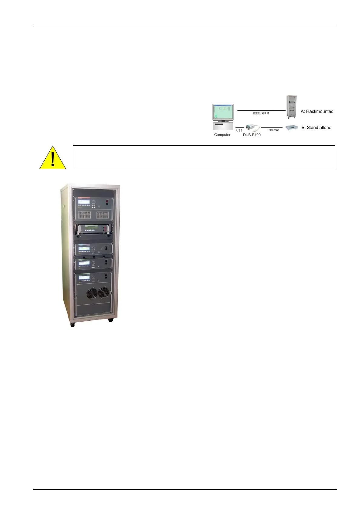
There are two solutions to connect the computer to the AutoWave.
- IEEE connection
- Ethernet connection
Both interface connections are applicable. Depends of the implementation EM Test propose the
IEEE or Ethernet interface.
iso.control software uses the IEEE interface. Ethernet interface is not supported by iso.control.
Connection to
A : Rack with ISO equipment ( IEEE )
B : Stand alone equipment ( Ethernet )
iso.control software uses the IEEE interface. Ethernet is not supported by iso.control
When setting up the test national and international regulations
regarding human safety have to be guaranteed.
It is recommended to connect the simulator to the ground reference
plane of the test set-up.
The generators of the series 200, UCS, LD, PFS and VDS can be
linked together to a fully automotive test set-up.
The set-up communicates via the IEEE/GPIB bus and is controlled by
ISM ISO software.
For setting up the system see the following figures:
Each generator can be operated individually as a single equipment.