EM TEST AutoWave
Manual for Operation V 5.9.1 30 / 45
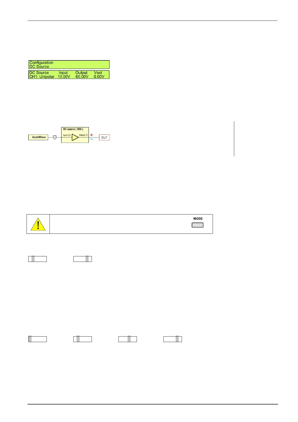
DC Source
Parameter to control the connected voltage source. This setting must be done for each channel CH1...CH4 with
a connected voltage source. AutoWave calculates automatically the correct output signal for controlling the
source.
Channel Selected output channel for setting the parameters
Source Source design for polarity output
Input U Max. input signal to control the power supply from
AutoWave ( individual each channel)
Output U Max. output signal of the power source to the DUT
Vset Manually setting DC output voltage of each channel.
(Vset ≤ Output)
Channel CH1, CH2, CH3, CH4
Source Unipolar , Bipolar
Input U Voltage range [ 0V ... 10.00V ] step 0.01
Output U Voltage range [ 0V...999.99V ] step 0.01
Examples for VDS
Unipolar
10.00V
30.00V or 60.00V
Mode of value setting
The user has a choice of two modes to edit values for voltage and frequency parameters.
The “normal” mode is the usual one, and is done in two steps:
- first step to setup the integer part
- second step to setup the fractional part.
The “all step editor” mode selects each digit from left to right and the value is parsed sequentially.
Toggle between the two edit modes with the button MODE
“Normal” Mode
30.00VSETUP30.00VSETUPnext value to setup
Available keys:
STOP: Ends the editing, discarding any changes
LEFT: Decrease the value with acceleration
RIGHT: Increase the value with acceleration
SETUP: Move from integer part to fractional part and then validate the setting
MODE: Change editing mode to “All Step Edition”
Note: In this mode, when you are setting the integer part, the fractional is set to zero.
“All Step Editor” Mode
30.00VSETUP3 0.00VSETUP30.00VSETUP30.00VSETUPnext value to setup
Available keys:
STOP: Ends the editing, discarding any changes
LEFT: Decrease the value with acceleration
RIGHT: Increase the value with acceleration
SETUP: Move the edited digit step by step from the left to right position / validate the setting
MODE: Change editing mode to “Normal”
Note: in this mode, any acceleration on LEFT or RIGHT key is disabled.