EM TEST AutoWave
Manual for Operation V 5.9.1 7 / 45
6. Cursor key "
" "
"
Cursor Key with the following functions
- Scrolling in the menus
- Setting the values up / down
7. Setup
Menu button for the device configuration menu.
See Chapter
3.2.2. Setup
Menu
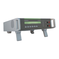
8. LED output active channel CH1 to CH4
LED display for indicating the active output channels.
Depends of extension 2 or 4 channels are built in.
Example:
CH 1 : Default channel for the battery power supply.
CH 2 : Auxiliary DC power for dips
CH 3 : Auxiliary channel for Ford specs.
CH 4 : Auxiliary channel for Ford specs.
9. LED display input channel 1 + 2
The LED indicates the state of the measuring channel
CH1 and CH2.
LED Status
OFF : Standby
ON : Recording
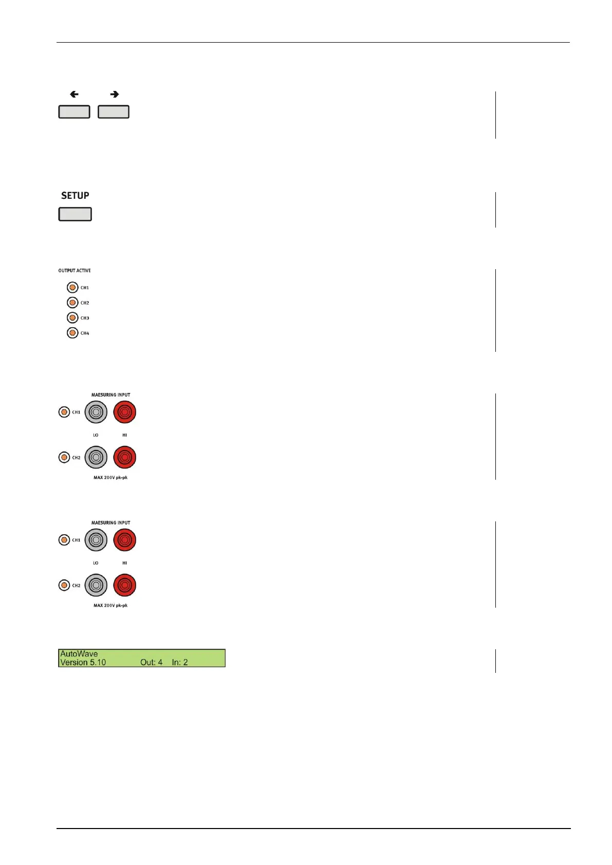
10. Measuring input channel 1 + 2
Input plugs for the two measuring channels CH1 and
CH2
Maximum input voltage is 200V peak - peak
11. Display
LCD display 2 x 40 characters