Introduction
1-3
About DAE2P and DAE3P disk enclosures
The DAE2P/DAE3P uses FC-AL link control cards to manage disks
and I/O traffic between enclosures. A DAE2P supports 2- or 4-gigabit
disks and 2-gigabit data transfer to and from disks on a Fibre Channel
loop called a back-end bus. DAE3P enclosures can support 2- or
4-gigabit disk modules and operate at either 2- or 4-gigabit bus speed.
2 Gb processors, enclosures, and disk modules cannot support or operate on
a 4 Gb bus. The DAE2P and DAE3P are externally identical except for
a distinguishing "4GB" label on the back of DAE3P enclosures.
Any DAE2P or DAE3P includes up to fifteen 3.5-inch disk modules.
Simple serial cabling provides easy scalability. You can interconnect
disk enclosures to form a large disk storage system; the number and
size of buses depends on the capabilities of your storage processor.
Highly available configurations require at least one pair of physically
independent loops (A and B sides of bus 0, sharing the same
dual-port disks). Other configurations use two, three, four, or more
buses. You can place the disk enclosures in the same cabinet, or in one
or more separate cabinets. High-availability features are standard.
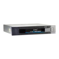
The DAE2P/DAE3P includes the following components:
◆ A sheet-metal enclosure with a midplane and front bezel
◆ Two link control cards (LCCs)
◆ As many as 15 disk modules
◆ Two power supply/system cooling modules
The power supply and system cooling components of the power/cooling
modules function independently of each other, but the assemblies are
packaged together into a single field-replaceable unit (FRU).
Any unoccupied disk module slot has a filler module to maintain air
flow.
The LCCs, disk modules, power supply/system cooling modules,
and filler modules are field-replaceable units (FRUs), which you can
add or replace without tools while the array is powered up.
The enclosure can continue running with one operating power
supply and a single functional LCC. At least three of the four system
cooling blowers must be running correctly for continuous operation.
Figures 1-2 through1-4 show the disk enclosure components. Details
on each component accompany the figures. Where the enclosure
provides slots for two identical components, the components are
called component-name A or component-name B, as shown in the
illustrations.