1-8
DAE2P/DAE3P Hardware Reference
About DAE2P and DAE3P disk enclosures
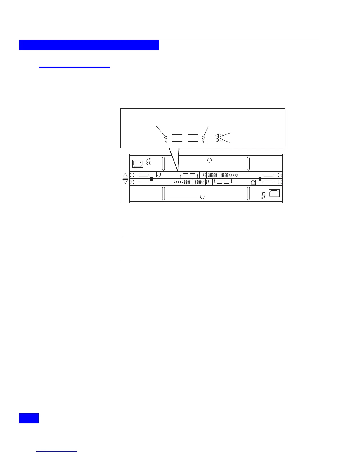
Link Control Cards (LCCs)
An LCC supports and controls one Fibre Channel bus and monitors
the DAE2P/DAE3P.
Figure 1-7 LCC connectors and status LEDs
A blue Link Active LED indicates a DAE3P enclosure operating at four
gigabits. The Link Active LED(s) is green in DAE2P enclosures, and DAE3Ps
operating at two Gb.
The LCCs in a DAE2P/DAE3P connect to other Fibre Channel
devices (processor enclosures, or other DAEs) with twin-axial copper
cables. The cables connect LCCs in a storage system together in a
daisy-chain (loop) topology.
Internally, each DAE2P/DAE3P LCC uses FC_AL protocols to
emulate a loop; it connects to the drives in its enclosure in a
point-to-point fashion through a switch. The LCC independently
receives and electrically terminates incoming FC-AL signals. For
traffic from the system’s storage processors, the LCC switch passes the
input signal from the primary port (PRI) to the drive being accessed;
the switch then forwards the drive's output signal to the expansion
port (EXP), where cables connect it to the next DAE in the loop. (If the
target drive is not in the LCC’s enclosure, the switch passes the input
signal directly to the EXP port.) At the unconnected expansion port
(EXP) of the last LCC, the output signal (from the storage processor)
is looped back to the input signal (to the storage processor). For traffic
directed to the system's storage processors, the switch passes input
!!
!!
!
EXP PRI
EXPPRI
#
!
EXP PRI
EXPPRI
#
A
B
EMC3226_revised
Expansion Link
Active LED (Green/Blue)
Primary Link
Active LED (Green/Blue)
Fault LED (Amber)
Power LED (Green)
!
EXP PRI
EXPPRI