Connecting the DAE2P/DAE3P to the back end bus
2-13
Installing a DAE2P/DAE3P
The figures in this chapter show configurations with DAE2P/DAE3Ps as
the only disk-array enclosures. Environments with a mix of DAE2 and
DAE2P/DAE3P enclosures follow the same EA, bus balancing, and
cabling conventions whenever possible and practical.
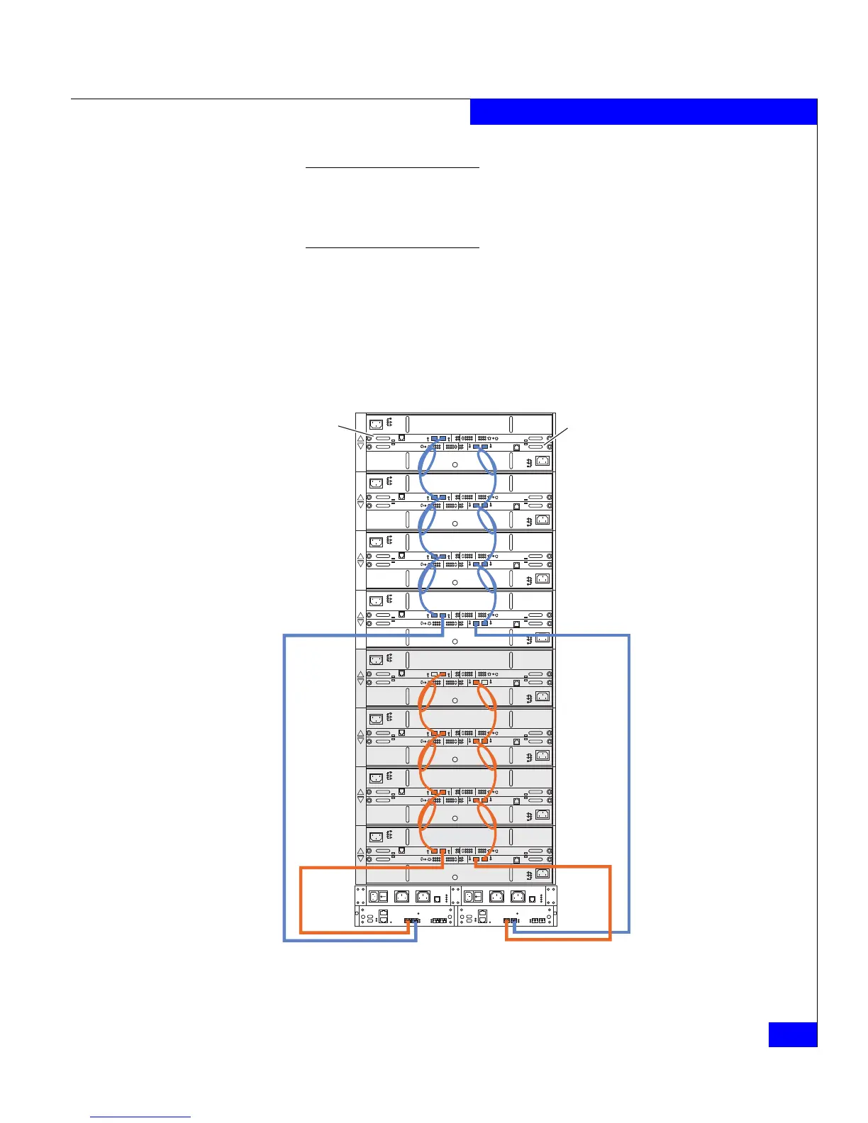
The configuration example in Figure 2-6 shows a CX3-series
Model 40 storage processor enclosure (SPE3) below eight DAE3P
disk-array enclosures. Each of the eight devices supports two
completely redundant loops. Note that the external device
connects to the Primary disk enclosure connectors, and
subsequent enclosures connect in an Expansion-to-Primary chain.
Figure 2-6 Cabling disk enclosures together — two Fibre Channel buses
!!
!!
!
EXP PRI
EXPPRI
#
!
EXP PRI
EXPPRI
#
A
B
!!
!!
!
EXP PRI
EXPPRI
#
!
EXP PRI
EXPPRI
#
A
B
!!
!!
!
EXP PRI
EXPPRI
#
!
EXP PRI
EXPPRI
#
A
B
!!
!!
!
EXP PRI
EXPPRI
#
!
EXP PRI
EXPPRI
#
A
B
!!
!!
!
EXP PRI
EXPPRI
#
!
EXP PRI
EXPPRI
#
A
B
!!
!!
!
EXP PRI
EXPPRI
#
!
EXP PRI
EXPPRI
#
A
B
!!
!!
!
EXP PRI
EXPPRI
#
!
EXP PRI
EXPPRI
#
A
B
!!
!!
!
EXP PRI
EXPPRI
#
!
EXP PRI
EXPPRI
#
A
B
SPS ASPS B
LCC B LCC A
EMC3412
Bus 1
Bus 0
Bus 1
Bus 0
EA0/Bus 0
EA1/Bus 0
EA2/Bus 0
EA3/Bus 0
EA0/Bus 1
EA1/Bus 1
EA2/Bus 1
EA3/Bus 1