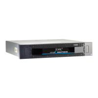
Disk modules
1-9
About DAE2P and DAE3P disk enclosures
signals from the expansion port directly to the output signal of the
primary port.
Each LCC independently monitors the environmental status of the
entire enclosure, using a microcomputer-controlled FRU
(field-replaceable unit) monitor program. The monitor communicates
status to the server, which polls disk enclosure status. LCC firmware
also controls the LCC port bypass circuits and the disk-module status
lights.
LCCs do not communicate with or control each other.
Each LCC has four status lights. These status lights are described in
“Monitoring disk enclosure status,” in Chapter 3.
Captive screws on the LCC lock it into place to ensure proper
connection to the midplane. You can add or replace an LCC while the
disk enclosure is powered up.
Disk modules
Each disk module consists of one disk drive in a carrier. You can add
or remove a disk module while the DAE2P/DAE3P is powered up,
but should exercise special care when removing modules while they
are in use.
DAE2P and DAE3P disk modules support dual-port FC-AL
interconnects through the two LCCs and their cabling; SATA
modules include a paddle card that provides a bridge between Fibre
Channel and SATA signals.
With some configuration restrictions, you can integrate and connect Fibre
Channel and ATA (Advanced Technology Attachment) DAE2 enclosures
with DAE2P/DAE3Ps within a storage system, but you cannot use ATA disks
within a DAE2P or DAE3P. (DAE3P SATA disks will not work in a
DAE2-ATA enclosure.)
A DAE3P enclosure can include Fibre Channel or SATA disk
modules, but not both types; DAE2P enclosures do not support SATA
disk modules.You can visually distinguish between module types by
their different latch and handle mechanisms and by labels on each
module. 4 Gb Fibre Channel drive carriers include a label that
indicates they can operate at 2/4 Gb; 2 Gb drive labels list capacity
and spindle speed only. SATA drive labels list type, capacity, and