EasyManuals Logo

EMC VNX Series Hardware Information Guide

EMC VNX Series
170 pages
To Next Page IconTo Next Page
To Previous Page IconTo Previous Page
Page #19 background imageLoading...
Page #19 background image
System component description
EMC VNX8000 Hardware Information Guide 19
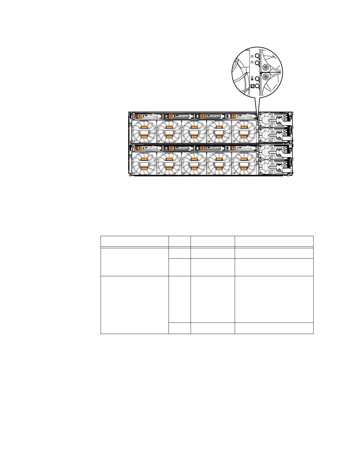
Figure 7 Example of SP power on, SP chassis (enclosure) fault, SF fault, and SP unsafe to remove
LEDs
Table 4 describes the SP and SP chassis (enclosure) status LEDs as shown in Figure 6 on
page 17 and Figure 7 on page 19.
CL5214
Table 4 VNX8000 platform SP and SP chassis (enclosure) status LEDs
LED Color State Description
SP power (see Detail 1 in
Figure 6 on page 17 and
exploded view in Figure 7 on
page 19)
Blue On Powered up
Off Powered down
SP chassis (enclosure) fault
(see Detail 1 in Figure 6 on
page 17 and exploded view
in Figure 7 on page 19)
Amber On Fault
•Power (PSU or SPS)
Environmental (fans)
•I/O modules or LCCs
•SP
CMI, SFP, Resume PROM
Off Operating normally

Other manuals for EMC VNX Series

Questions and Answers:

Question and Answer IconNeed help?

Do you have a question about the EMC VNX Series and is the answer not in the manual?

EMC VNX Series Specifications

General IconGeneral
Management InterfaceUnisphere
Drive SupportSAS, NL-SAS, Flash (SSD)
RAID LevelsRAID 0, 1, 3, 5, 6
Protocols SupportedFibre Channel, iSCSI, NFS, CIFS
Data ServicesDeduplication, Compression, Snapshots, Replication
ProcessorIntel Xeon
Operating SystemVNX Operating Environment (block), VNX File Operating Environment (file)

Related product manuals