14
Reference Manual
00809-0200-4410, Rev BC
Mounting and Connection
July 2017
Mounting and Connection
3.1.2 Physical description
The Gateway electronics is enclosed in a polymer housing. The front of the enclosure has connections for
power, Ethernet, and serial communications. The unit is designed to be mounted on a DIN rail inside an
electronic enclosure.
3.2 Mounting
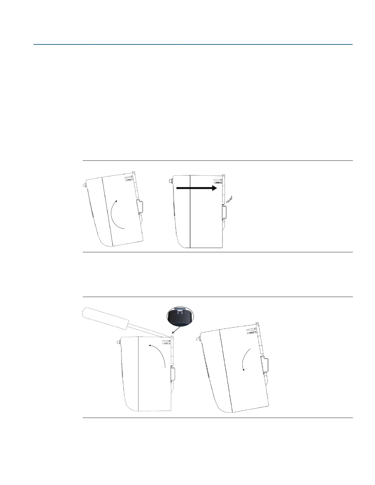
The unit can be snapped onto a DIN TS35/7.5 or TS35/15 rail system. To clip the unit onto the DIN rail,
see Figure 3-1.
1. Tilt the unit at a slight angle allowing the lower lip of the chassis to catch the bottom of the DIN rail.
2. Apply pressure forward to snap the back of the unit securely onto the DIN rail.
Figure 3-1. Installing
To remove the unit, see Figure 3-2.
1. Place a flat or rounded object (such as a screw driver) into the DIN clip and apply a slight pressure
downwards on the object.
2. Once the unit is released from the DIN rail pull backwards and down to successfully disengage.
Figure 3-2. Removing

 Loading...


