Introduction
Parameter
x.00
Parameter
description format
Keypad and
display
Serial
communications
CT Modbus
RTU
PLC Ladder
programming
CTSoft Menu 0
Advanced parameter
descriptions
Menu 8
Commander SK Advanced User Guide 117
Issue Number: 9 www.controltechniques.com
The thermistor going short circuit will not damage the drive.
When Pr 8.35 is set to th, the mode button will need to be pressed four times to return the drive display to status mode. This ensures that this setting
is saved.
When terminal B7 is set as motor thermistor input, Pr 1.41 is no longer assigned to terminal B7 therefore analog reference 2 is no longer selected.
Analog reference 1 should be used.
There is no parameter to display the motor temperature.
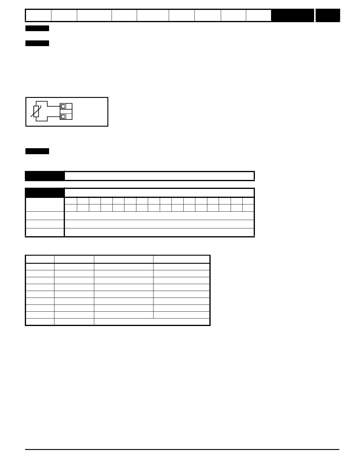
Connect the motor thermistor between 0V and terminal B7.
Figure 10-22 Connection diagram
In modes 2 and 3, terminal B7 will function as a frequency input as described in menu 3.
The frequency input destination parameter, Pr 8.25 will be scaled by the maximum reference frequency, Pr 3.43. For example, (from default), setting
Pr 8.25 =1.21 and Pr 3.43=2kHz, with a frequency input of 1kHz on terminal B7, Pr 1.21 will be 25Hz.
The amplitude of the frequency input must be above 15V peak to peak. The threshold voltage is 10V.
This parameter offers a simple control of Pr 8.21 to change the functionality of the digital output.
Its function is used to set the value of Pr 8.21 to one of the parameters listed below.
A user wishing to change the digital output to something other than the one’s listed above or using the terminal as an input, must first program this
parameter to 8. Pr 8.21 should then be programmed to the desired unprotected parameter.
8.36 to 8.40 Unused parameters
8.41 Digital output control (Terminal B3) {35}
Coding
Bit SP FI DE Txt VM DP ND RA NC NV PT US RW BU PS
1 111
Range
n=0(0), At.SP(1), Lo.SP(2), hEAL(3), Act(4), ALAr(5), I.Lt(6), At.Ld(7), USEr(8)
Default n=0(0)
Update rate Action on exit of edit mode
Value Display Function Parameter Setting
0 n=0 At zero speed Pr 8.21 = Pr 10.03
1 At.SP At speed Pr 8.21 = Pr 10.06
2 Lo.SP At minimum speed Pr 8.21 = Pr 10.04
3 hEAL Drive ok Pr 8.21 = Pr 10.01
4 Act Drive active Pr 8.21 = Pr 10.02
5 ALAr General drive alarm Pr 8.21 = Pr 10.19
6 I.Lt Current limit active Pr 8.21 = Pr 10.09
7 At.Ld At 100% load Pr 8.21 = Pr 10.08
8 USEr Allows Pr 8.21 to be set up by user.
0V
Motor thermistor
input
T1
B7