Menu 12 Introduction
Parameter
x.00
Parameter
description format
Keypad and
display
Serial
communications
CT Modbus
RTU
PLC Ladder
programming
CTSoft Menu 0
Advanced parameter
descriptions
154 Commander SK Advanced User Guide
www.controltechniques.com Issue Number: 9
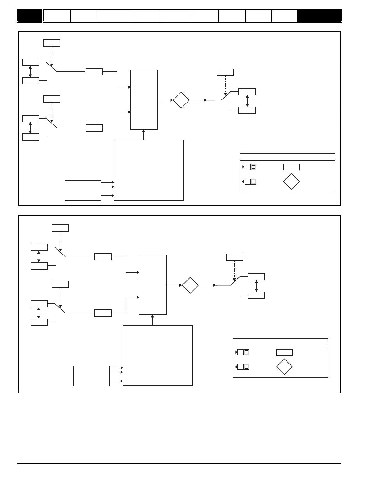
Figure 10-37 Menu 12B logic diagram
Figure 10-38 Menu 12C logic diagram
21.51
01.01
0.00
21.51
1.01
12.08
Source 1
21.51
1.01
0.00
21.51
1.01
12.09
Source 2
12.13
Scaling
12.14
Scaling
Input 1
Input 2
12.12
1.01
21.51
0.00
21.51
1.01
12.11
Destination
Output
Variable selector modes
= Input 1
= Input 2
= Input 1 + Input 2
= Input 1 - Input 2
= (Input 1 x Input 2) / 100
= (Input 1 x 100) / Input 2
= Input1/( +1)
= Input 1 via Ramp
= |Input 1|
= Input 1
12.10
0 - 12.12
1 - 12.12
2 - 12.12
3 - 12.12
4 - 12.12
5 - 12.12
6 - 12.12 12.15s
7 - 12.12
8 - 12.12
9 - 12.12
12.15
Variable
selector control
12.15
XX
XX
Key
Read-write (RW)
parameter
Read-only (RO)
parameter
Input
terminals
Output
terminals
XX
XX
The parameters are all shown at their default settings
21.51
1.01
0.00
21.51
1.01
12.28
Source 1
21.51
1.01
0.00
21.51
1.01
12.29
Source 2
12.33
Scaling
12.34
Scaling
Input 1
Input 2
12.32
1.01
21.51
0.00
21.51
1.01
12.31
Destination
Output
Variable selector modes
= Input 1
= Input 2
= Input 1 + Input 2
= Input 1 - Input 2
= (Input 1 x Input 2) / 100
= (Input 1 x 100) / Input 2
= Input1/( +1)
= Input 1 via Ramp
= |Input 1|
= Input 1
12.30
0 - 12.32
1 - 12.32
2 - 12.32
3 - 12.32
4 - 12.32
5 - 12.32
6 - 12.32 12.15s
7 - 12.32
8 - 12.32
9 - 12.32
12.15
Variable
selector control
12.35
XX
XX
Key
Read-write (RW)
parameter
Read-only (RO)
parameter
Input
terminals
Output
terminals
XX
XX
The parameters are all shown at their default settings