Damcos LPU: LPU Power Control System Service Manual
February 2017 SM 8000-100-01 Ed 04
121
LPU Power Control Description
Power controlled LPU has internal control ensuring stop of electrical motor, when the valve has
reached end position or if the valve is blocked in intermediate positions.
LPU-S can maintain an open position on a spring actuator by restarting the pump in case of a pres-
sure loss.
The control of the units in the system is carried out with hardwire in star connection from a relay- or
PLC substation.
Each LPU is connected to a control console with one cable only and is controlled only by the operat-
ing voltage.
In power controlled versions the valve position signals (switches or 4-20 mA loop powered) are led
directly to the substation.
Position Indication Signals
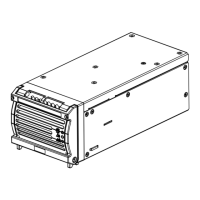
The position indicator is built into the pump block with internal wiring from position indicator to the
circuit board mounted in the LPU electrical encapsulation.
Potentiometer for analogue position indication, or 2 micro-switches for end-position indication are
available.
• For analogue position indication signals, two wires are required.
• For ON/OFF indication signal, one common wire and one wire each for open and for closed signal
are required.
• ON/OFF switches are limited to 2.5 VA resistive load. Please refer to separate data sheet
• Direct connection to the potentiometer is also possible. The potentiometer must be used as a 3-
wire voltage-divider..
Position indication signal: Continuous: 4-20mA 24V DC
2 wire transmitter
ON/OFF: Max 2.5 VA switches
Cable:
Damcos recommends standard cable, 7 x 1.5 mm²
Continuous: Min. 5 x 1.5 mm?
ON/OFF: Min. 6 x 1.5 mm?
Cable diameter:
ø 12.5 - 20.5 mm
 Loading...