Damcos LPU: LPU Power Control System Service Manual
February 2017 SM 8000-100-01 Ed 04
125
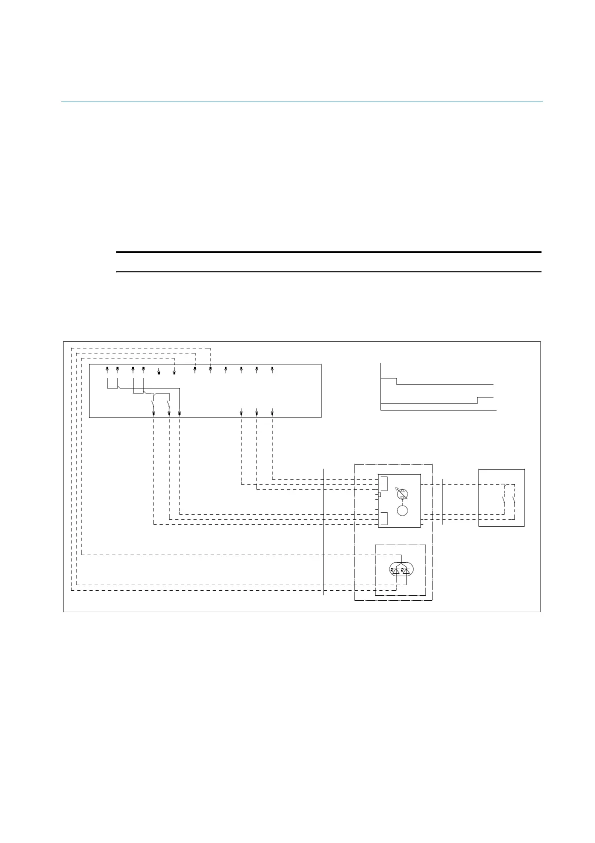
LPU with LED Position Indicator
The LED position indicator in the top cover on the LPU can be powered by:
• Directly via the ON/OFF position indicator (commonly DPI-E), if the signal back to the inputs may
be 24VDC respectively 0V.
• From the ON/OFF position indicator outputs in PD527, with the 0VDC connected to the com-
mon anode of the LED.
• From customer specified output.
Note! Under all circumstances, 24VDC power to the LED must be available in LPU.
Diagrams for Power Controlled LPU with LED Position Indicator
Option 1 - PD527 controlled power LPU with LED indicator
1%#.
.0%6-&9999
7"-7&/0
999
.9999
#-6&
#-6&
7%$
#308/
#308/
065
.9999
7
065
7
$-04&
01&/
&4%
$-04&
'&&%#"$,
$-04&
N"
$-04&
01&/
01&/
01&/
'&&%#"$,
"-"3.
$0.
$0..0/
'&&%#"$,
$
.139$9,7
YNNÞ
)JHI
-PX
)JHI
-PX
$MPTFE
-&%3FEMJHIU
-16%
.
108&3$0/530--&%
$0.
$-04&
01&/
$0.
.0503
7"-7&
7%$7"$
#3*%(&
-16
"$56"50303
#6-,.06/5&%
3&%(3&&/
015*0/
-16$07&3
)JHI7-PX7
$
.139$9,7
YNNÞ
(3&&/3&%8*3&
(3&&/8*3&
3&%8*3&
%1*&
0QFO
-&%(SFFOMJHIU
%1*&
7BMWF1PT
*/%*$"503.06/5&%
0/5)&"$56"503
0
$
 Loading...