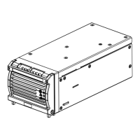
Damcos LPU: Operating LPU-D 2a Service Manual
February 2017 SM 8000-100-01 Ed 04
75
Operating LPU-D 2a
Hydraulic Diagram LPU-D
To open valve
When the motor and solenoid valve are activated the oil is sucked from tank through the suction fil-
ter to the pump and pumped through the solenoid valve and the pilot operated check valve (13) to
the actuator port B. This causes the actuator to open the valve. The oil from actuator port A flows
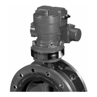
back through the pilot operated check valve (5) (which is opened by the pressure in the B-line) and
returns through the solenoid valve to the tank.
When the valve is fully open, the pressure rises to 150 bar, which causes the pump safety valve to
open so that the oil flows back to tank. The motor and the solenoid valve are then de-energized.
The actuator is now hydraulically locked in position by the pilot operated check valves.
Safety/Actuator relief valve
In case of a major rise in temperature, the pressure may rise. This will not cause any problems
because of the actuator relief valve (6) and (11), which will open at approx. 225 bar.
1. Tank for hydraulic oil
2. Suction filter
3. Electrical motor
4. Pressure switch
5. Double pilot operated check valve,
closing side
6. Actuator relief valve, closing side
7. Quick connection for hand pump,
closing w/filter
8. By-pass valve
9. Double-acting actuator
10.Quick connection for hand pump,
opening w/filter
11.Actuator relief valve, opening side
12.Tank filling valve
13.Double pilot operated check valve,
opening side
14.Solenoid valve
15.Pump safety valve
16.Pressure controlled flow adjustment
17.Variable displacement pump
 Loading...