Damcos LPU: Pump pressure adjustment for LPU Service Manual
February 2017 SM 8000-100-01 Ed 04
85
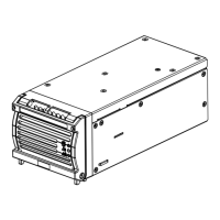
Pump pressure adjustment for LPU
Warning! Parts inside housing of LPU are connected to 230 Volts, please do not touch these parts
without power supply securely OFF.
1. The pressure gauge is mounted on quick connection B (nearest to the motor) of the LPU. For
LPU-D the adjustment can also be carried out with the pressure gauge on quick connection A,
and thus the LPU shall only receive a ”Close”-command during adjustment.
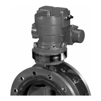
2. Adjustment of the pump pressure is carried out with a 5 mm Allen key with ball head. The adjust-
ment screw is placed near the pressure switch (the one near the LPU-front in LPU-D).
3. The pressure has to be set to 150 bar. As there are some tolerances in the system, the pressure
might be varying, that’s why the pressure is set to 150 bar to assure a running pressure of 135
bar at the actuator. Tightening the screw will rise the pressure, loosening the screw will lower the
adjusted pressure.
4. For Power- controlled LPU: To obtain a longer operating time of the motor than standard 7 sec-
onds, the pressure switch cables to the specific pressure switch (for “B” it is the pressure switch
near the pressure adjustment) can possibly be dismounted from the print. These lines are from
print card connected to 220 Volt. The motor must be operated for max. 10 minutes.
5. For P-NET controlled LPU: To obtain a longer operating time of the motor than standard 7 sec-
onds, the indicator cables to the specific terminal can possibly be dismounted from the print.
The motor must be active for max. 10 minutes.
6. When the actuator is in end position, the pressure can be read on the pressure gauge, while the
motor is running.
7. The pressure is adjusted to approx. 150 bar. Then the motor is stopped, pressure released and
motor is started again for fine adjustment, if any.
8. After final adjustment the pressure gauge is dismounted, and the cables to the pressure switch/
indicator are mounted again.