1.2.1 T-Slot Transducer assembly and mount
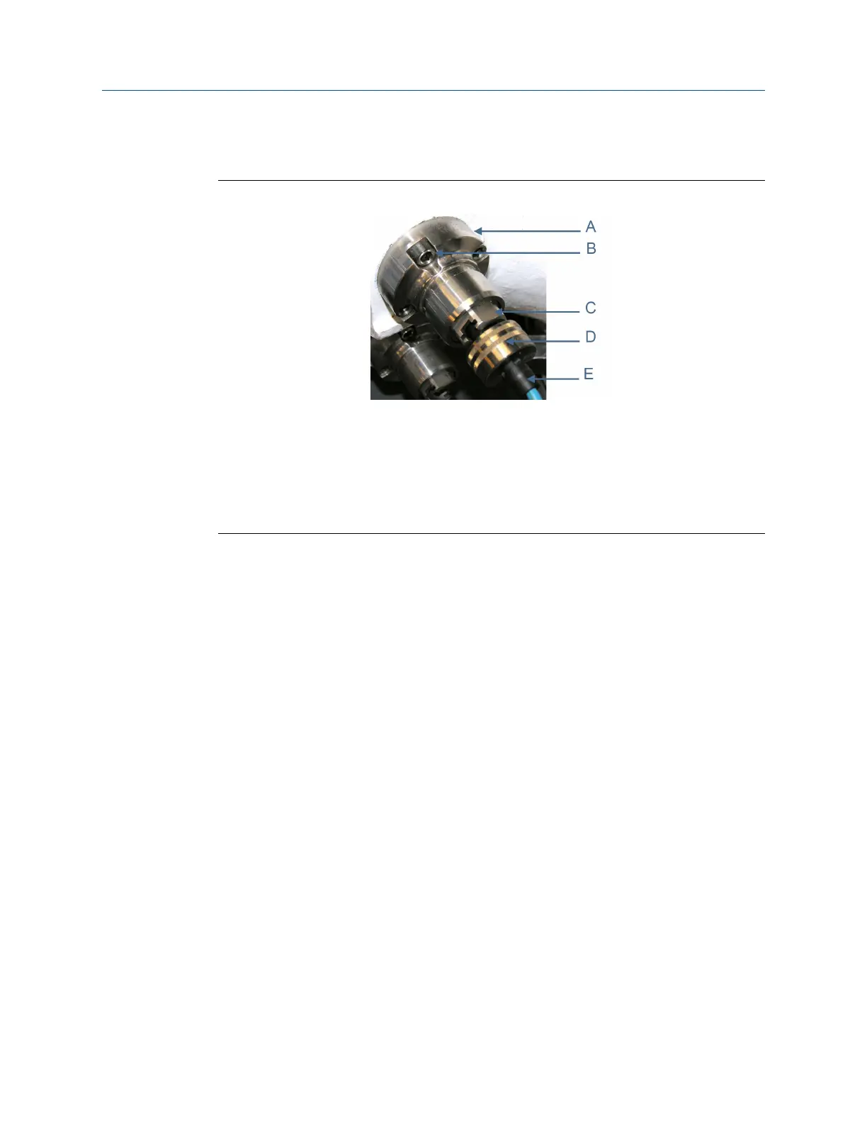
Figure 1-1: T-slot transducer mount and holder
A. Transducer mount
B. Captive screws
C. T-slot transducer holder
D. Cable nut
E. Chordset
Procedure
1. Slowly vent all line pressure on the 3410 Series Gas Ultrasonic Meter to atmosphere.
2. Disconnect transducer cable from the transducer holder.
3. If installed, remove the mount cover by loosening the two mount cover captive
screws.
4. Loosen the T-Slot transducer assembly with a 1 1/4 inch (32 mm) socket. Carefully
remove the T-Slot transducer assembly.
5. Place a label on the transducer assembly to marks its location (i.e., Model 3414-A1,
A2, B1, B2, C1, C2, D1, or D2; 3412-A1, A2, B1, B2; or 3411-A). Port locations are
marked on the transducer cable as well as on cast meter housings.
6. Inspect the transducer mount threads and ensure they are clean and free of debris.
7. Apply a small amount of Nickel antiseize compound (P/N 3-9960-134) to the
threads of the Hydrotest plug (P/N 1-360-01-212) from kit (P/N 1-360-01-220) and
install it into the mount. JuniorSonic
™
kit part numbers are listed below.
• JuniorSonic
™
SP Field Hydrotest Kit (P/N 1-360-01-221)
• JuniorSonic
™
DP Field Hydrotest Kit (P/N 1-360-01-222)
8. Repeat Step 1 through Step 6 for the other transducer(s) being careful to note the
location of each transducer in the meter assembly.
9. Run the field hydrostatic test.
10. Reverse the steps above to reinstall the transducers into their appropriate ports.
Before reinstalling the transducer assemblies, ensure the transducer ports, mounts,
and transducer holders are clean and free of debris. Apply a small amount of Nickel
Maintenance and Troubleshooting manual Maintenance
P/N 3-9000-769 June 2019
Maintenance and Troubleshooting manual 13

 Loading...


