Note
Do not over tighten the retainer.
7. Plug the keyed chordset into the transformer assembly.
8. Thread the cable nut onto the transducer retainer. Ensure the cable nut threads are
aligned correctly and hand-tighten.
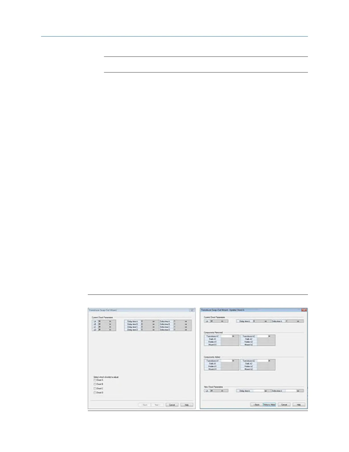
3.3.5 Modifying the calibration parameters for T-Slot
transducers
When transducer pairs, mounts, stalks or transducer holders are replaced, the
corresponding meter calibration parameters must be updated for accurate operation. This
means modifying the affected chord "L" dimension (LA... LD) (see Determining the “L”
Value below), average delay time (AvgDlyA... AvgDlyD) and delta delay time (DltDlyA...
DltDlyD) using the Daniel MeterLink Transducer Swap-out Wizard (see Figure 3-8).
Average delay time and delta delay time modifications
The transducer pair average delay time and delta delay time are located on the transducer
pair calibration sheet. These values must be downloaded to the appropriate meter data
points (AvgDlyA... AvgDlyD, DltDlyA... DltDlyD). The lengths of the transducers are also
included on the calibration sheet and are etched on the transducers. Likewise the lengths
of the stalk assemblies, transducer holders, and mounts are etched on the individual
components. The length of the meter body is found on the original calibration sheet
supplied with the meter.
Determining the “L” value
The value "L" is determined by adding the length of the meter body to the lengths of the
two mounts and subtracting the lengths of the transducer holders, stalk assemblies, and
transducers. This value should be written to the appropriate meter data points for each
chord that received new transducers (LA... LD). See Equation 3-1 for the “L” dimension
calculation.
Figure 3-8: Daniel MeterLink Transducer Swap-out Wizard
Meter repairs Maintenance and Troubleshooting manual
June 2019 P/N 3-9000-769
64 Gas Ultrasonic Flow Meters

 Loading...


