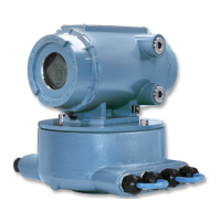
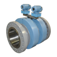
5. Remove the two bolts holding the Base Enclosure cover to the Transmitter
Electronics Enclosure using a 6mm Allen wrench.
6. Lift the Transmitter Electronics Enclosure from the Base Enclosure. It may be
necessary to remove the ground lug wire and loosen the conduit connections prior
to removal.
7. Carefully prop the Transmitter Electronics Enclosure to the side.
8. Use a flat-blade screw driver and disconnect the transducer wiring terminal block
from the Acquisition Module (see Figure 3-20).
9. Place the Transmitter Electronics Enclosure in a clean dry area. Be careful not to
dislodge or damage the enclosure gasket.
10. Remove the transducer cable wires from the terminal block and slide the existing
cable through the Base Enclosure gland.
3.8.2
Install transducer cables
Procedure
1. Use the existing cable and cut the new cable (Daniel P/N 1-360-01-310) for each
chordset to same length.
2. Insert the keyed chordset into the transducer holder. Make sure the keyed parts are
correctly aligned.
3. Screw the cable nut onto the transducer holder turing clock-wise until hand-tight.
Ensure the threads are correctly aligned and do not overtighten the cable nut.
4. Route the cable through the gland on the Base Enclosure and pull the cable up
through the Base Enclosure to allow enough slack to strip the cable wire.
5. Strip the outer insulation, outer shield, and inner insulation to just inside the cable
gland using a wire stripper. Verify that insulation of individual wires were not cut
while removing outer layers. Strip each wire 1/4 inch and wire them to the
Acquisition Module terminal block. Check the label number (i.e. A1) on the
Acquisition Module and match it with the label on the cable. Securely tighten the
mounting screws of terminal block J1 and J2 as shown in Figure 3-20.
Maintenance and Troubleshooting manual Meter repairs
P/N 3-9000-769 June 2019
Maintenance and Troubleshooting manual 83

 Loading...


