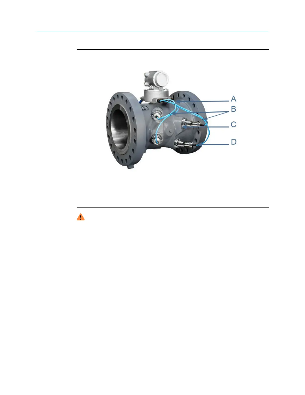
Figure 3-19: Daniel 3410 Series Ultrasonic Gas Flow Meter transducer cables and
ports
A. Base enclosure transducer cable glands
B. Cable ties (two locations)
C. 3410 Series Ultrasonic Meter transducer port
D. Transducer mount and transducer cable nut and chordset (P/N 1-360-01-310)
WARNING
CRUSHING HAZARD
During meter installation or removal, always place the unit on a stable platform or
surface that supports its assembled weight.
Failure to comply could allow the meter to roll, resulting in serious injury or equipment
damage.
3.8.1
Remove transducer cables
The meter body ports are identified by stamped or cast lettering adjacent to the
transducer port (i.e. Model 3414 - A1, A2, B1, B2, C1, C2, D1, and D2; Model 3412 - A1, A2,
B1, and B2; Model 3411 - A1 and A2).
Procedure
1. Remove power to the meter.
2. Unscrew the cable nut from the transducer holder and then, pull the cable chordset
from the transducer holder (see Figure 3-19).
3. Cut the tie wraps for the transducer cable you are replacing.
4. Use a wrench and loosen the cable gland (where the transducer cable enters the
Base Electronics Enclosure) until the transducer cable freely slides inside the gland.
Meter repairs Maintenance and Troubleshooting manual
June 2019 P/N 3-9000-769
82 Gas Ultrasonic Flow Meters

 Loading...


