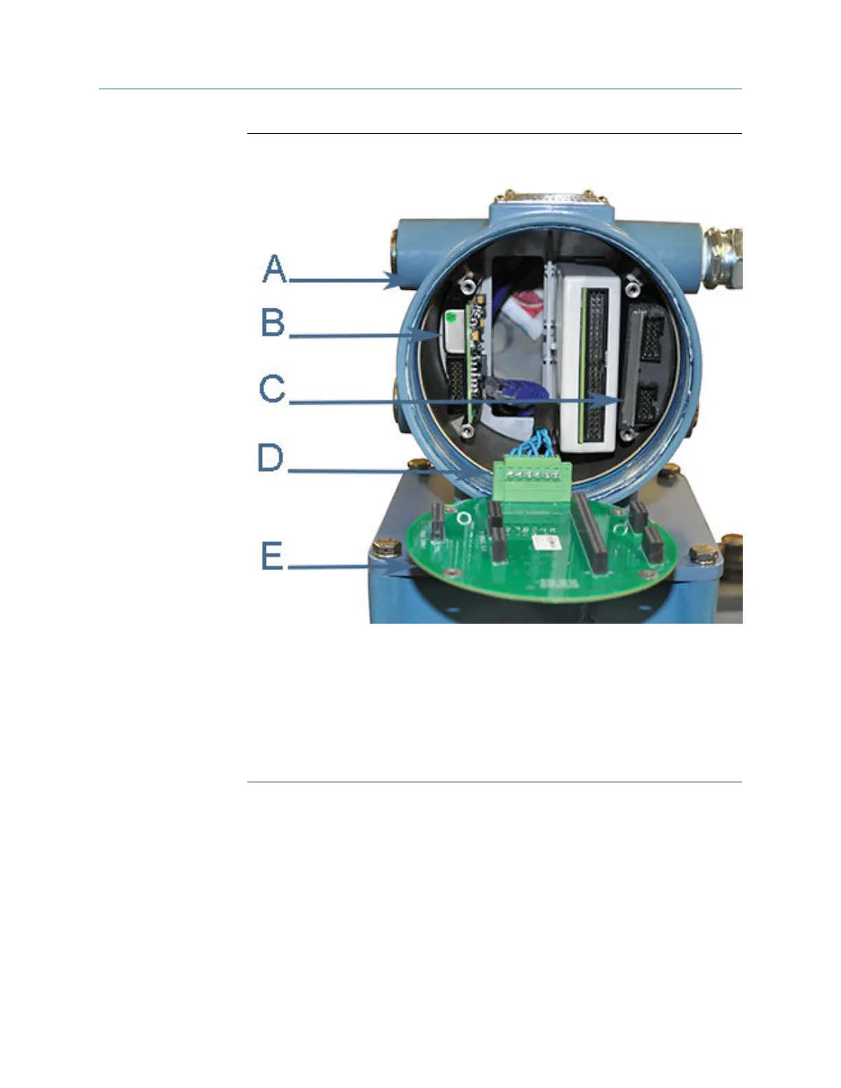
I.S. Barrier board replacementFigure 3-14:
A. Non-terminal end of Transmitter Electronics Enclosure
B. Power Supply board
C. I.S. Barrier board (inside the Guide Plate)
D. Acquisition cable
E. Backplane board
6. Remove the I.S. Barrier Board from the Guide Plate on the right side of the
enclosure.
7. Install the new I.S. Barrier board onto the Backplane Board and seat the Power
Supply board onto the Backplane board.
8. Insert the Backplane, I.S. Barrier board and the Power Supply Board into the
enclosure.
9. Fully seat the CPU Module and Optional I/O Module onto the Backplane Board.
10. Attach the Backplane to the enclosure standoffs with the four Phillips head screws. If
the Local Display Module is installed on the Backplane, use a flat blade screw driver
and install the four flat-head screws into the enclosure standoffs.
Meter repairs
Maintenance and Troubleshooting manual 39

 Loading...


