6. Loosen the three Allen setscrews with a 1/16” hex driver securing the transducer
assembly and stalk, if installed. Carefully remove the old transducer by pulling it
from the T-Slot transducer holder assembly without rotating.
Important
Record the “L” dimension of the removed transducers which is used to update the meter
configuration after all of the transducers are replaced. Make sure you have the report sheet
containing the “L” dimension, Delay Time, and Delta Delay Time for the replacement pair of
transducers to use during the Transducer Swap-out procedure in Daniel MeterLink.
7. Clean the transducer holder with a dry cloth.
3.2.2 Install transducers
1. Ensure that the Daniel 3410 Series Ultrasonic Gas Flow Meter transducer port,
mount, and T-Slot transducer holder assembly are clean and free of debris.
2. Apply a small amount of Molykote 111to the female contacts on the transducer.
3. Install the transducer assembly into the transducer holder or into the stalk (if
required). The parts are keyed and can only be assembled one way. As the
transducers are installed into the holder or stalk assembly, they must be labeled
with a marker for future reference (i.e., transducer #1 would be A-1 and transducer
#2 would be A-2).
4. Use a 1/16” hex driver to equally tighten the three Allen set screws on the
transducer holder to secure the transducer assembly and the stalks (if installed).
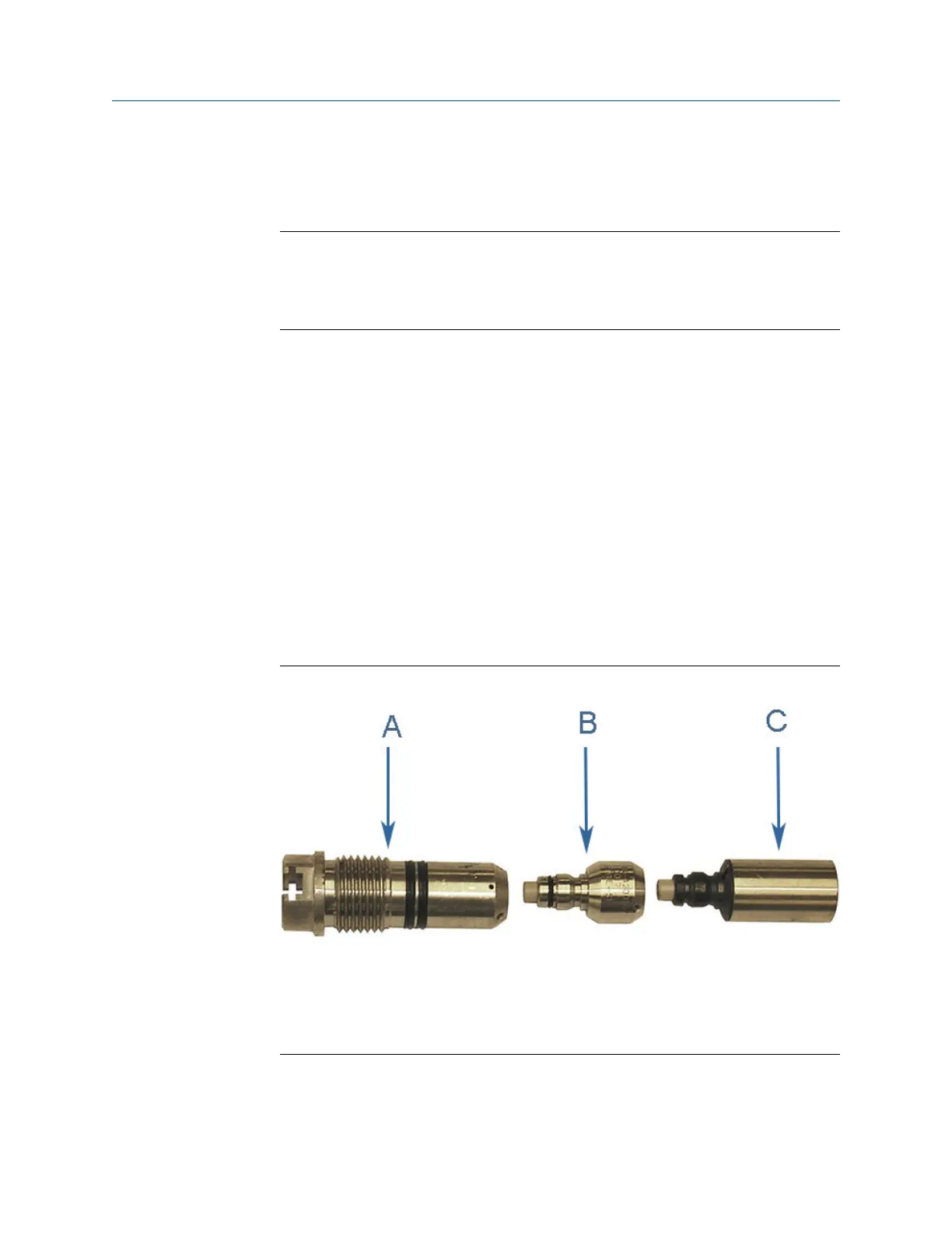
Transducer holder, stalk and transducer assemblyFigure 3-2:
A. Transduce holder
B. Stalk
Transducer assembly
Meter repairs
Maintenance and Troubleshooting manual 17

 Loading...


